![]()
| About Bolt Products | Bolt Products Homepage | Bolting Information | Catalogue |
Welcome to the Bolt Products General Information Pages.
These pages are not specifically related to our products, they are more a general collection of information, tests, thoughts and tips on the subject of bolting.
If anyone has anything they feel would interest others to be included here then please mail it to sales@bolt-products.com
Part 1 - Bolting and equipment
Part 2 - Stake tests
Part 3 - Tests, glueing and glue-in bolt design
Part 4 - Calculating bolt strength
Part 5 - Testing Bolts
Part 6 - Pitons
Part 7 - Belay Device theory
Bolting
The amount of extra equipment you will need will depend on the amount of bolting you want to do and the style. Bolting an occasional short project on a cliff with easy top access is different from developing a complete cliff and ground-up bolting of long, overhanging or multi-pitch has different requirements again.
Everyone has his own methods but the the recommendations below are my own preferences and roughly the system used by most of the bolters I know and are a good basis to work on.
Wear the oldest clothes you have!
Belays and Ropework.
Anchors
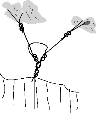
Normally (and preferably) you are going to be bolting with access from above so you need an anchor point for the rope.
If you´re lucky there will be plenty of natural nut placements, threads, trees etc, personally I don´t like relying purely on nuts and especially cams as you cannot see what is happening to them as the rope moves and jerks around. I try to arrange at least one thread even if I have to drill it myself.
If there are no natural belays but solid rock I like to use drilled threads and carry a long (400mm) 12mm drill for this. Often you can find a natural feature in the rock that only needs a bit of drilling, otherwise you will have to drill through a corner starting the hole well away from the edge, something like 150mm is good. Look out for cracks, bedding planes and veins which could weaken the thread and always use a nutsling back-up or two threads. Round off the holes to protect the gear. Either thread with dyneema slings or my preference is to directly thread with the ends of the rigging rope; less gear to be damaged, fewer links and the rope is more robust than slings.
The two setups above can be a time consuming faff and you need to carry even more gear to the top of the crag, quick and efficient is to place a couple of bolt-ins. I use cheaper steel bolts in pairs, 8mm are plenty strong enough,and remove the hangers later (drill the holes deeper so you can drive them in flush with the surface after use). If your going to bolt a lot of routes along a cliff then it´s worth spending a bit of time installing a line of bolts a few metres back and around 5m apart, this saves a lot of time and complication later.
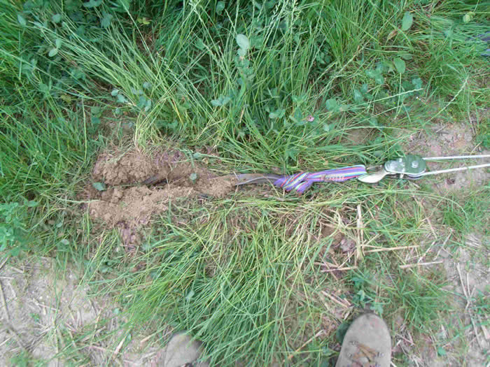
Of course not all cliffs have convenient lines of trees or even rock at the top and here you will need stakes, familiar to most sea cliff climbers and for the uninitiated often a cause for concern.
Below you will find stake tests, what to use and how to install them.
Set-up
Get a set-up rope! 15m of static rope makes life so much easier. We normally buy 10mm polyester rope from the local hardware store when we are abroad to save on baggage and dump it when we leave. Don´t buy nylon as it is stretchy. Tie the two ends into your anchor points and then figure of eight on a bight in each strand to clip to.
Your working/set-up rope is going to wear over the edge of the cliff and you should protect it. Depending on the situation I have two ways to do this:
Rope protectors. You can buy these ready made but they are expensive and another thing to transport, we obtain ½" bore black plastic water pipe locally which is dirt cheap (if not free) and incredibly robust. 1 to 1,5m long and flatten one end with your hammer so it grips the rope.
Bypass. I tie a figure of eight on a bight above and below the section that will be on the rock and clip a wide tape sling in to take the working load and abrasion, in Greece where I developed a number of cliffs the tops were extremely sharp I used a length of stainless cable with end loops swaged in for this. The only difficulty with this method is abseiling over the edge is very awkward, using a rope protector is easier as you can slide it into the correct place after you as you abseil over the edge.
Working Rope
Baggage allowances being what they are I usually struggle with a oldish but still good lead rope, if it gets trashed by rockfall or abrasion then it is not such a loss.
If at all possible use a 10,5 or 11mm static rope. The difference it makes working and jumaring is well worth the extra weight and hassle and they are much more robust.
Harness
Most of the time your normal climbing harness will do fine but if you are on longer overhanging routes where all your weight is on the leg loops for a while you will soon notice numb feet and dead legs, the onset of thrombosis. This can cause permanant damage or be fatal but is avoided by standing in a foot loop for a while. For serious bolting a proper rope working sit harness such as the Petzl Navaho is by far the better choice, much wider leg and back, more robust and metal clip-in points. Once you have tried one you won´t go back!
Abseiling and Ascending
You are going to do a lot of this, mostly carrying loads of gear so you need a good, safe and easy system. Most guys I know and myself run an expedition ascender such as the Petzl Ascension with one foot loop above a GriGri on the harness. It takes a bit of getting used to ascending with the GriGri but the ability to switch from ascending to descending quickly is very useful. You can use a shunt or similar for the foot loop but removing it from the rope is a hassle whereas with an ascender its a doddle. The ascender should be joined into your harness as well using a long knotted sling. Lanyard when you remove it, back-up if you trigger the GriGri accidentally and a cows tail all in one.
Runners.
Unless the routes are straight up and down and not overhanging you usually need to provide a few temporary runners to keep in place, especially while you are drilling as you are pushing yourself away from the cliff all the time.
A basic set of nuts and maybe a few cams are enough along with a few thin slings for threads etc along with enough quickdraws. And of course a hook or two! A skyhook (or bathook as they have become) is usually ideal for holding you in place and saves tired aching fingers.
Bolting From Below
Some climbers do this because of an ethical standpoint, otherwise it is because the cliff is too high, has no top access or is too steep. Whatever the reason this is very hard, slow work and to be avoided if possible. Depending on the difficulty of the climbing and the rock it is either climbinmg a route with a lot of gear and bolt placing as you go or it is a full-on aid seige.
If it is at all possible then lead the route as a normal trad route with aid if nescessary and then set up a working rope, leading encumbered with the drill and the rest is a pain when the routes are harder.
I have done a number of on-sight 100m+ routes leading and bolting at the same time and it is horribly hard, you are tring to climb with an extra 10 to 15kg of awkward gear and holding on while drilling is a finger killer. Another problem is normally you end up placing the bolts where you can get gear in to rest on, not where the best or most desirable place would be and have to add extra bolts later.
One technique is to have the drill, bolts etc on a long (ca 5m) lanyard and a fifi hook. This you leave on the last bolt and haul up when you get a resting place. The drill will get battered to death this way so make a protector from a cut down 5l oil canister for it.
If you need to aid the route posting your belayer at the bottom for a few hours of utter boredom is a great way to change climbing partners so I place a bolt or drill a thread at the foot of the crag, tie one end of the climbing (not static) rope to it and put it through a GriGri on my harness to self belay, the rest of the rope is flaked out in the rope bag.
Using all your normal trad rack and a couple of hooks aid up placing protection bolts as you go and of course clipping them. If the route is of any decent standard you will probably run out of gear placements somewhere, you can use shallow drilled holes and bathook, small bolt-ins, removable bolts or, as I prefer, studs or rivets. The pattern we have developed and sell uses a 6mm hole 25 or 30mm deep and can be easily removed and re-used, they hold surprisingly well (600kg+) and I have fallen on them when hook placements above have failed.
Drilling
The normal choice is between hand, battery, mains electricity and petrol drills, the decision on which is mostly related to the number of holes required in a session and practicality.
Hand Drills
Normally the drill is held in a rubber covered bit holder which you strike repeatedly with a hammer while rotating by hand. Slow, laborious and difficulty drilling an accurate hole are the drawbacks but for people who only want one or two holes or cannot justify carrying the weight of the alternatives there is little choice. In some areas of the world this may be the only way you are permitted to drill.
Battery Drills
By far the most popular method, probably over 90% of bolts are placed this way today. There is an enormous variety on the market today but before picking up a cheapie at your local do-it-yourself shop here are a few guidelines.
Drilling method
Rotary, hammer or rotary hammer? Unless you are using diamond drills normal rotary drilling is ineffective in rock so you need to consider percussion or rotary hammer;- normal percussion drills basically vibrate the drill chuck forwards and back at quite a high speed using a system of cam plates, they tend to be noisy, power hungry and vibrate your hands to death but are cheap so if you only want a few holes these are the way to go. Rotary hammer drills using the Bosch SDS+ (Special Direct System) bit driving system where a sliding weight strikes the drill bit forwards in the bit holder as it rotates are the universal choice for serious drilling nowadays and for any substantial work these are the best choice.One of the best indications of the drills effectiveness is the impact energy measured in Joules with the more popular models given below BUT this is more a measure of how fast the holes are drilled than how many holes you get per charge.
Which Battery Type
With few exceptions these drills are running on 24 or 36 volt battery systems with various advantages claimed for all but in the field little difference is observed except the 36´s drill a bit faster.
The batteries are either NiCad, NiMH or Li-ion with plenty of arguments for all types, the use of cadmium being heavily restricted in Europe nowadays NiCad´s are rapidly becoming extinct though they have the longest lifespan. Li-ion batteries are lighter for the same power but some of their durability characteristics are a problem, NiMH roughly in the middle (these are what drives the Toyota Prius).
Most manufacturers offer more than one capacity (rated in Ah) battery, typically you can choose between a 3Ah `brick´ down to a 1.6Ah one, most convenient is one large and one smaller one as a spare or where you want to save weight.
Mains Drills
If you have the luxury of mains electricity or are willing to lug a generator around you can go straight up to a drill with around 7-9 J hammer energy and really rip into the rock. Just about every power tool company makes a range of these with various features and power outputs, if you are in the construction industry you can probably get use of a Hilti or check out the local hire centre. These, and the petrol powered drills below are really only an option for clubs or similar groups that want to place/replace a lot of bolts at one venue and have enough manpower to carry the equipment.
Petrol Drills.
In the days when battery drills were slow and ineffective these were popular and if it´s a lot of holes quickly these are still a great bit of kit however they are big, heavy, noisy and hard to get hold of.
The best known is probably the Pionjär with a similar looking one available from China, another mean looking tool is the Cobra Combi from Atlas Copco-24kg, 60J hammer energy but at €6000 you won´t see many of these on the cliff!
In The Field
Grease-keep the SDS grooves clean and lightly greased, your machine will last longer and drill faster.
Storage- if you don´t use your drill for a while it will perform badly to start with, at a guess about 50%, after a few charge/discharge cycles it will come back to normal, this happens to my old NiCad´s as well as the new Li-ion´s despite all the manufacturers claims.
Charging- when the charger says the battery is full remove it for 5mins to allow it to cool and then replace it in the charger, this normally jerks a bit more in, in the case of my Bosch about 7% which is near enough another hole. Keep the battery and charger in the shade while charging, in direct sunthe termperature sensor may stop the charging cycle.
Charging- Charging from a portable generator or an inverter often doesn´t work due to the modified sine wave these give out, mostly the charger lights indicate it is working but in reality it does nothing so you need to check before you buy a power supply.
How many holes- after „what´s it cost“ the most frequent question, my tired old Bosch gives me between 13 and 17 holes in medium limestone (12mm dia X 80mm deep) and a newer generation Makita around 17 to 20ish. Rock is very variable so it´s hard to be more definate.
What to buy-Battery Drills
This is a somewhat Eurocentric review of the market, particularly in the U.S.A there are other manufacturers active but I have no experence of their products. Prices were at time of writing.
Hilti-For many years the Hilti was the Rolls Royce of drills with the best drilling action and a very useful remote battery adaptor for overhangs but at least three very active climbers I know have now replaced them, unreliable batteries along with horrific prices for repairs being the main reason. Hard to recommend them at these prices.
Bosch Annihalator (GBH 24 VRE) Looking at the specs an apparently outdated machine but solid, compact and reliable at the right price. I´ve used one for 8 years now and it´s still going strong on the original battery but it is also a bit heavier than the modern generation.
3.8kg. 1,3J hammer energy, 3.0Ah NiCd batt. Currently around €500. or 2 X 2,6 NiMH batts.€480.
Bosch GBH 36 V Li- The newest generation from Bosch with Lithium-ion batteries, I use one of these at work and it definately drills faster than the above but too new to know about reliability.
4.3kg, 3.0J hammer, 2X 2Ah batts for ca €675.
Makita BHR200SJ- Nickel Metallhybrid,
1,7J hammer, 4,3kg, 3,3Ah battery for ca €600.
Makita BHR200WAE- Several people I know have junked their Hilti´s for these and are happy with them.
3,8kg, 2,1J hammer, 2X 2,0Ah batts for ca €510. Definatly the most drill for your buck today.
DeWALT DC234KL- A step up in quality than the above manufacturers with a performance to match the large Bosch and price as well. DeWALT do a large range of battery drills and other tools with various interchangeable battery systems, useful if you want others tools as well as they sell them without battery etc.
3,8kg, 2,5J hammer, 2 X 2,2Ah Li-ion batts for around €680.
Metabo KHA 24- Coming soon from Metabo is their first 24V drill, the perfomance should be comparable to the others here and Metabo quality is usually as good as it gets.
3,7kg 2,2J hammer, 2 X 2,2 Ah Li-ion batts. €670.
If you only want to drill routes and for general handyman work my recommendation would be the Makita BHR200WAE, if you use a drill and other battery tools for work then DeWALT or Metabo would be my choice, partly for the versatility and mainly the quality.
Drill Bits.
Curiously I can´t find a comparison test for drill bits so have taken a completely unscientific straw poll of all the people I know who drill routes and others in the construction industry. Basically the concensus is that they are all much the same. One reason for this is that there are only a few manufacturers of the carbide tips, another that nearly all manufactureres are working to the same quality standards. For our application all the claims for multi point, fast dust extraction, 30% faster etc seems to be irrelevant, I personally have tried almost every type and found no discernable difference though the bits from Bosch are good and those from Hilti appear to be best but at a price. The only advice I can give is buy the cheapest reputable brand and always carry a spare, sometimes they catch and chip the carbide tips.
A couple of useful tips;- the best way to depth mark drill bits is with an angle grinder or use paint, finger tape is o.k. but doesn´t last all day. Buy a really long drill(500-600mm) as well as the normal lengths, on overhanging rock they make drilling a lot easier and also come in handy for drilling threads. I normally carry a spare of each size I am using on me on the route in case I break a tip or drop one down the cliff.
Hole Cleaning Gear.
Before installing the bolt you must clean the dust out of the hole, mechanical bolts just need a bit of cleaning with a blower to remove the dust which can cause the sleeves to jam before pulling up but for glue-ins you must be fussy and clean the pores in the rock to allow the glue to mechanically bond. There have been plenty of tests done on this and especially using cartridge glues dirty holes are found reduce the pull-out strength by up to 90%.
Just blowing out is not sufficient for chemical fasteners.
The correct way is blow, brush out and blow again, with lung power being nowhere as good as a proper pump as well as keeping you a bit cleaner!
Suitable brushes and blowers are available from most fastener companies as well as ourselves.
Below is a photograph of a test series using various cleaning methods in a concrete block, identical bolts glued in with polyester and axially tested;
Top
Hole blown out with blower.
Pull-out 1060kg/10,4kN
Centre
Hole blown out with compressed air at 8 bar.
Pull-out 1560kg/15,3kN
Bottom
Hole blown, brushed and blown with blower.
Pull-out 3540kg/34,7kN
As you can see the better the cleaning of the hole the better is the adhesion to the test block and less glue remains on the bolt. (The glue tends to crumble under high load and falls off when extracted.)
Hammer
You will need a hammer to place bolts and also for cleaning the route, dedicated piton hammers are nice but pricey, something about 600g to 1kg and with a point or wedge at one end can often be found in a DIY store at a fraction of the price. Mine is one of these modified with an angle grinder to give a pick at one end. If possible weld a thick (6mm) stainless steel plate on the striking face, this stops unsightly rust marks on the bolt where you hit it. Metal handles are useful if you do a lot of bolting in hot climates, wooden handles shrink and loosen though you can soak them overnight in water.
Glue-gun Holster
At first glance a strange idea but believe me the stuff gets everywhere and if you let the glue gun dangle on its lanyard you get a tangled sticky mess on the rope or your leg. The glue can drip from the nozzle end and the outside of the nozzle is anyway smeared with glue
This is a great idea from my brother which makes life a lot more bearable and costs peanuts,
Get a length of 100mm plastic pipe about 300mm long. Drill a hole for an attatchment loop at one end and fix a carrier bag over the other to catch the drips and smears off the nozzle. As this pipe was corrugated ( it is sold as cable conduit)I used a cord and tanka but tape is just as good. When the bag is covered inside with hard glue just change it.
Route Cleaning Gear.
Depends on the locality and the cliff. Most of my bolting is done in the Med. on virgin cliffs and this is what we take:
Hammer
Nut Key
Cleaning Brush
Gardening Saw
Long Handled shears
Gardening/work gloves
Useful is a stonemasons adze, these have a long pick and an adze on the head and are just the job for cleaning out vegetated cracks.
Torque Wrench
For bolt-ins you need something to tighten them up. To get the right setting torque you want a 3/8 drive ratchet torque wrench which will cover the range for 10 and 12mm bolts. Set it to the correct reading and tape it up to stop it changing.
Bolt Bag
Some sort of bag to carry bolts, spare drills and nozzles etc is almost essential. Mine is an old harness bag converted and a shoulder strap is useful, in fact if you can find your dads old hippy bag it will be ideal! A carrier bag is useless, when you change drills the hot one melts straight through!
Recessing Bolt Heads
Some companies tell you to do this as well as bolting "experts" however it takes time, wears the drill bit and may weaken the placement in some kinds of rock. With a well designed bolt there are no advantages but one big disadvantage- recessing the head will prevent it being cut off at a later date and removal with a core drill.
![]()
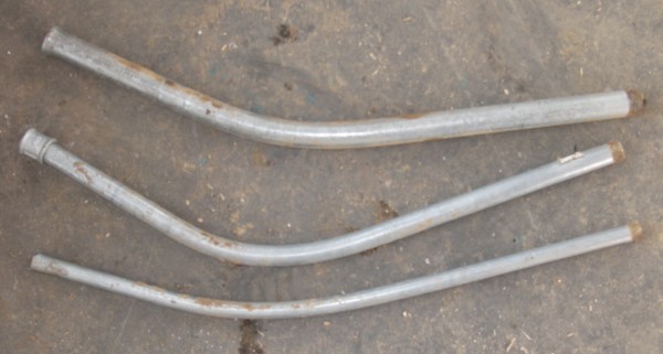
Stakes.
Maybe this is a strange thing to find on a bolt companies website but there you are. Call it public service! As it happens I´ve been abbing off these for the best part of 40 years and always wanted to know how strong they where, or not, as the case may be.
Stakes are more correctly called pickets and there used to be loads of information from the military all about them, from building bridges to tying up lines of horses, nowadays about the only use seems to be providing ground anchors for recovering stuck armoured vehicles with talk of 90,000lbs pull and such like so not very relevant to climbers. They are still used for rescue purposes but even then no hard and fast figures are available, the tendency is to repeat the line "pickets should be at least 3" in diameter, 6 ft long and driven 2/3 of the way in" which appears in boy scout manuals and the like.
Of course most of the need for pickets has been superceded by heavy machinery, a decent screw pile is installed in seconds or if needed just park something heavy and tie onto it. (We explored many of the chalk cliffs of Dorset using a Ford Anglia as an anchor.)
The modern answer is the ground anchor which is driven below the surface using a ramming bar and then put under strain to tip over and present a large area to resist extraction, these are incredibly strong but expensive and impractical for climbers and so we are left with good old stakes.
What to use.
This is a selection from our experience with stakes on the sea cliffs at Swanage since a long time ago!
Still the best are probably the old style road menders pickets, 1" hexagonal steel with an integral eye forged at the top. These had hardened points for driving through the road surface and are indistructable, you can see a few of these at the top at Swanage but don´t seem to be available anymore, they have probably been replaced by cones.
Next best would be old buck-rake tines so if there is any old farm machinery around have a look out, superb steel and virtually immune from rust. Ideal for rocky ground.
Angle iron is sort of o.k. but horribly prone to rust, after a few years there can be nothing left underground.
Road sign poles, another one which rusts away internally while you looked at it and horrific to hammer in.
Scaffold pipe used to be popular but you need a very big (sledge) hammer to drive in, especially if it is a bit stony.
Galvanised water pipe. Cheap as chips or normally free from any builders skip and amazingly durable this is the favourite nowadays. Needs a 2kg lump hammer to drive in.
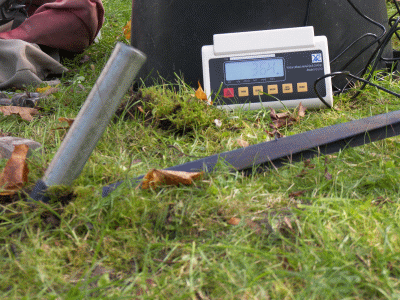
How Strong Are They?
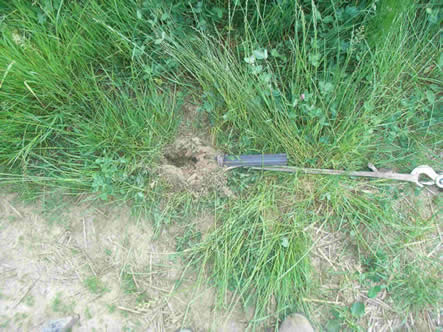
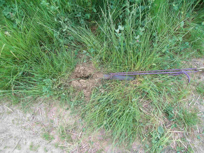
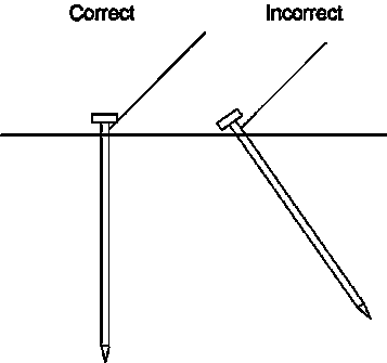
To satisfy my curiosity and entertain the kids one day I tested three different sizes of standard water pipe 800mm long driven to three depths- 400mm, 600mm and 800mm. These were installed at the generally recommended angle of 15° away from the load and pulled with a wire winch and load cell. The first tests were done in my back garden which is a waterlogged swamp with 400mm of soft soil over clay.
The tests were then repeated at a nearby farm, to the entertainment of the ducks, yard dog and the farmer, in some well compacted clay/sand mixed soil which has been an established nettle bed for over 40 yrs but with no tree roots, a good solid piece of dirt in fact.
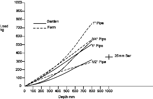
(The cross marked 25mm bar is from a test I found in sandy loam soil, as it didn´t bend like my 1" pipe in soft ground I think the result was relatively poor, maybe they need to bend to achieve full holding power?)
The first thing I noticed is that once they have started bending the pull resistance starts rising, with all the highest readings coming when they are bent about 20° past vertical and presumably have a moderate hooking action. The reason the 1" pipe didn´t perform as well as expected in the garden tests was that it did not bend but pulled through and out.
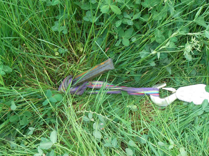
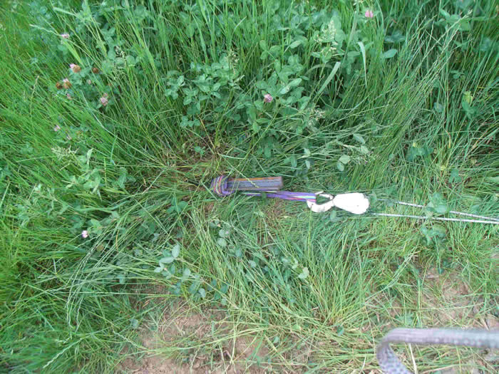
This what they looked like after the farm tests fully driven in and then pulled.
And this is why a clove or cow hitch on the stake is a good idea!
Conclusions
It seems the general distrust of ½" pipe is well justified but it looks like a piece of ¾" or 1" well in is pretty well bombproof from an abseil or top belay point of view. Something to retain the rope or sling at the end is a good idea, the joining nipples I tried mostly broke off as I hammered them in but maybe properly tightened up they would be better. A clove hitch on the sling or rope is also a good idea!
Of course the real load when abseiling is probably going to be less than one thinks, the friction of the rope over the typically rounded cliff edge must be huge. This will be the subject of another test in the future.
Stakes-Part 2
Further research and then some testing has thrown up some interesting facts, some of which are quite hard to believe.
Tension Posts
These are posts or stakes intended to be under permanent tension such as fence strainer posts. The ideal for these is a stake which doesn´t deflect under this load and so they are need to be very stiff and have a large bearing surface. As they are driven in they compress the earth around them and the area must be enough to prevent the load pulling the stake through the earth. Once they are overloaded the earth in front of them is pushed out of the way in a roughly cone shaped form.As you will see these aren´t really relevant to us.
Stake Anchors
These are what we are interested in, we don´t really care if the stake deflects, we want the maximum holding power and in this case it appears that stiffnes is of no relevance, in fact the more flexible the stake the higher its pull-out was in my tests. I had already noticed this in the first test but decided to test this further:-
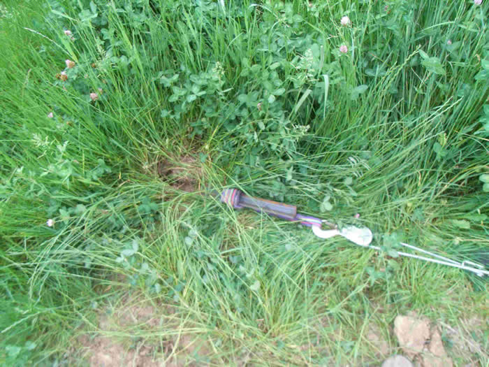
1" water pipe. 800mm deep. 15° Leant back installation. Same farm test area as above but drier soil. Pull-out resistance 940kg. Stake bent ca 45°
1" water pipe as above. 20mm steel bar inside. " 724kg. Stake bent ca 20° and cut through the soil.
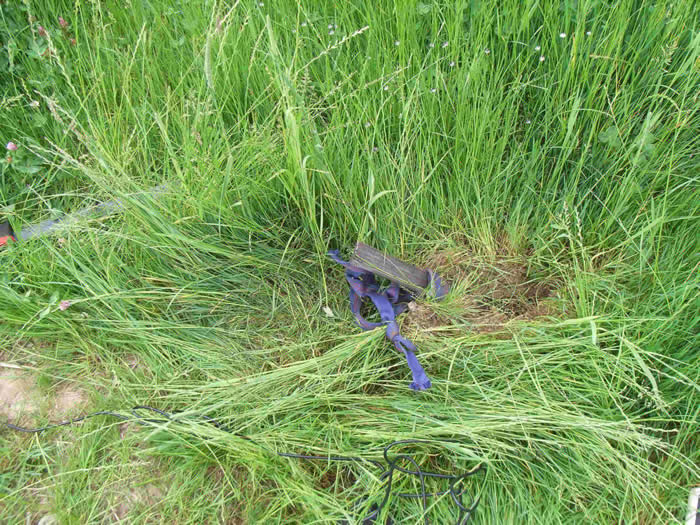
Intrigued I made up a set of pointed angle iron stakes 1m long with a ring welded around at 80cm to retain the sling and started pulling them.
The first was a 25mm angle with 3mm thick material.
This started bending at 380kg.
And looked like this at 670kg
Like this at 850kg (old sling had broken at this stage)
And like this at 1162kg (changed to shorter sling)
The peak force this one held was 1320kg before dropping progressively to 660kg before coming out.
And then to something really bizzarre. The usual recommended angle for single stakes (multiple ones are different) is 15°-20° back, that is 105°-110° to the force and this appears completely logical and instinctively what I would use. However some useful tent peg tests I found led me to investigate further, after all the industry that uses stakes a lot must be the marquee industry and these are tested for safety. A goldmine! They have industry training, standards and of course have done the testing. Unfortunatly the test results are in a very expensive book but the safety training brochures have what we want.
There you will find that the optimum angle is with the load angled at 45° upwards and in fact they give a reduction factor if you increase the angle. They show this so:
Even though I wasn´t convinced I performed the following test:-
Two stakes were installed. One 30mm angle 4mm material angled 45° forwards and another, 45mm angle 5mm material angled 15° backwards, both 800mm deep with my puller and load cell between.
Start of pull, the stake started to bend at 1180kg.
At 1320kg
And at 1560kg
At which point the doubled sling on the other end broke, as we´ve noticed in other tests the outer part cuts the inner part where the lie on top of each other on the shackle. This was a new condition 2000kg rated sling.
. 
As you can see the anchor stake is starting to bend.
The sling was replaced with a steel cable and I continued pulling, the stake finally failing at 1974 kg.
At this point the rain started so testing was discontinued, apart from the silage clamp test below.
Conclusions.
It is clear that the friction between the stake and the earth is what gives them ultimate extraction resistance, and this is born out by the lower values for water pipe which has a smoother surface. This was also noted in the tent pegs tests I read. This being the case then bendy anchors,and even more so, forward inclined ones will logically give higher values. A stiff anchor cuts a slot through the ground and thereby loses a sustantial amount of its contact area, the bendy ones still have a large surface area in contact lower down and hold better. The forward angled ones cut a much shorter slot as they bend down and keep even more area in contact.
A 30mm stake has a frontal area 1.2 x that of a 25mm one and so if pull-out resistance was only a question of resistance to cutting through the soil then we could expect the the 30mm stake to achieve 1,2x the resistance of the 25mm one or 1320 x 1,2 = 1584kg but as we have seen the 30mm one achieved 1974kg. If you take the total surface area for friction, that is back and front the relationship is still 1,2:1 so obviously more of the stake was working to achieve the higher result, as can be seen in the photo´s below.
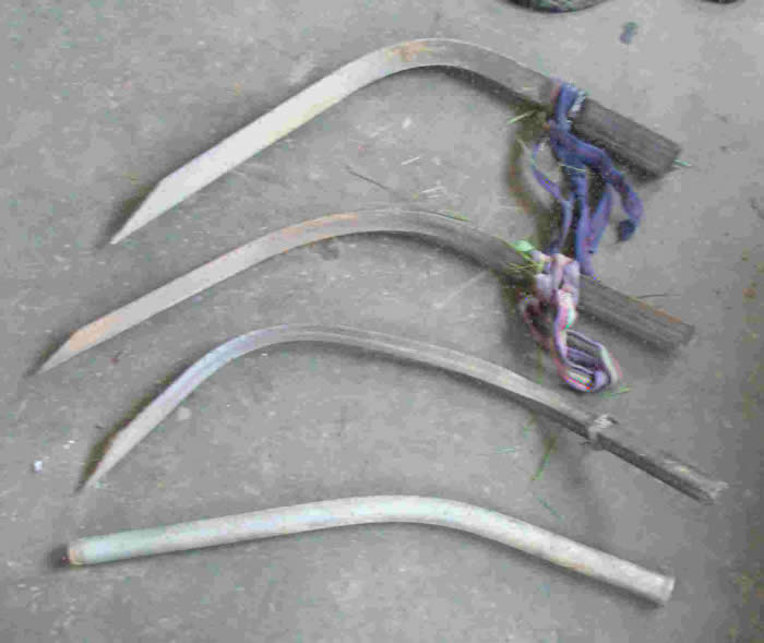
And they look like this;
Top- 45mm x 5mm angle- 1974kg but not pulled, note it has bent even more than the opposing stake below which was installed leaning forwards at 45°
30mm x 4mm angle-1974kg where you can clearly see the majority of the stake is still at its original installation angle whereas the one below cut down through the earth leaving considerably less area to provide friction.
25mm x 3mm angle- 1320kg
1" water pipe reinforced with 20mm bar-724kg
Drop Test for Seconds.
Therer are a few tests published for belay loads when seconds fall, the American Safe Climbing Association among others having done them but they are predominantly for direct drop or for toprope loadings. The typical sea cliff scenario is the rope down over a curved edge and there is a huge amount of friction. A 6m high vertically cut silage clamp seemed the ideal place with a nicely rounded top so on with the oilskins, anchor the rope 5m back with the load cell and over I go. A bit of abseiling got 74kg (I weight 90+kg) and a 2m drop pulled 150kg. I stopped this test as I was concerned that the heap would collapse on me if I fell further and because I was wet through and stinking! This test will be continued in a more suitable place.
What do climbers need?
Well this is what I tried to identify with my silage tests but it´s going to be hard to be sure, location is everything. Our experience is that almost anything will do, stake failure being virtually undeard of. The UIAA standard for toprope anchors calls for 20kN but for cliff top anchors this is obviously well over the top, in fact mountaineering experience over the years has shown us that a stout chap firmly braced is all it takes. As a completely personal view with all the usual disclaimers I think 250kg would be adequate and something like 500kg would give a good reserve and acceptable. We know for instance that the 1/2" water pipe anchor (in rock) has been at the top of Grandmas Groove, Swanage for nearly 40 years and is still doing fine service after countless falls, some from me!
Further Reading
You can find formulas for different earth hardness, stake depth correction, diameters etc in this handy booklet, it is copyright and I will try to get permission to reproduce it but for the moment the link is http://www.tentexperts.com/pdf/StakingGuide_LowRes.pdf
To be continued!
![]()
Glue-in bolt Design.
.
Some Tests
Testing. The EN-959 requires a fall resistance of 25kN and an extraction resistance of 15kN,
the UIAA-123 requirements are 25kN fall and 20kN extraction.
It should be noted that bolts do not come under the category of Personal Safaty Equipment and therefore do not require independant testing and carry no CE mark.
In my case these tests were carried out using a hydaulic extraction tester calibrated to plus/minus 10%
All figures given below are for axial extraction (worst case).
Testing Equipment.
The D.A.V. tester was purpose built by the Technical University of Munich and is a hydraulic extraction system.
My tester was purpose built by myself and is also hydraulic as is that built by my friend in Austria.
The only suitable commercially available and certified tester I can locate is manufactured by Com-Ten Industries (www.com-ten.com) who produce a nice looking portable (25lbs) extraction tester rated to 2700kg for USD 2295.(Hand Operated Digital Portable Fastener Tester)
Typical test results.
Taken from „Axiale Auspressversuche bei Fortbildungen der Sicherheitsforschung in Donautal und in Frankenjura 1“. Deutscher Alpenverein. (available as pdf) and test result obtained by myself and collegues.
Raumer Expressanker M10 A2 ss (sliding sleeve on cone). 8 tests, 30kN, 36kN 15kN (rock failure), 30kN, 36kN, 36kN 15kN, 9kN (sleeve failed to expand sufficiently)
Our Test on similar design. Cheap Greek hardware shop product!10mm Mild Steel.80mm long. 3 tests. All failed below 8kN. Bolt broke at thread.
Our Test M10 A2 ss. 80mm long. 6 tests. All withstood 36kN before bolt failed at thread.
Fischer Expressanker (similar design to Raumer Express) mild steel. 75mm long. 2 tests. 35kN, 12kN (rock failure.). I used a M16 x 150mm one of these as an anchor when testing one day and radially loaded it failed at 45,86kN.
Upat Expressanker (similar design). M12 mild steel. 5 tests. 37kN (rock failure), 55kN, 31kN rock failure. 50kN. 56kN,
Our Test. M12 A2 ss. 62kN.
Petzl Long Life (hammer-in) 12mm A2ss. 7tests. 23kN (extracted) 22kN (extracted) 15kN,
12kN, 13kN, 27kN,27kN (all rock failure.) These are rather short at 47mm which resulted in rock failure.
Salewa Bühler Bolt. 12mmdia. A2ss. 7 tests. Long series. 52kN, 52kN, 56kN, 48kN, 27kN (last two- karabiner linking tester failed, all others glue failure) Short series.30kN (glue failed) 47kN (broke out)
Our Tests. Multiple tests (ca50). Normal straight Bühler type. A2 ss. 12mm dia hole. 6mmdia rod. 80mm long. Worst test 36kN (rock failure) 43kN (glue failure)
Improved design. Between 48kN and 52kN.
Ushba Bolt (Buhler type glue-in developed for Thailand to overcome the corrosion problems)
Material. Titanium:10mm dia. 5 tests. 9kN, 9kN, 10kN (all broke at eye weld), 24kN, 34kN.
Fischer Highbond threaded anchor. M12. A4 ss. 6 tests. 47kN (rock failure) 81kN, 72kN, 53kN(rock failure) 60kN, 73kN.
Own Design Lower Off . 12mmdia ss. Unable to extract from rock. Tester failed at 72kN.
There are some good tests done by the D.A.V. (Deutscher Alpine Verien) on various bolts and also on different glues, but only published in German. I will try to get permission to translate them for posting here.
Design
Practically bolts consist of two parts: The „leg or legs“ glued into the rock and the „eye“.
Considerations are; strength, material cost, manufacturing/tooling cost, ease of use, hole required, rock strength, durability, regulatory requirements (EN and UIAA).
Bolt Shaft or Legs.
To understand the requirements for the „legs“ it is first important to understand that stainless steel displays very poor adhesion characteristics, an often used value for epoxies to stainless is 7N/mm², this being achieved by scrupulous cleaning and „wet“ abrasion with 100grit abrasives and epoxy. Not a scenario likely to be seen at your local crag! Figures for epoxy bond strengths are hard to find but for example 3M produce an aerospace certified epoxy which achieves a value of ca. 11.8N/mm² in shear. This is naturally after adequate surface preparation, a typical example of which would involve de-greasing, grit blasting and de-grease/etch. (One recommended etching solution is 47%conc. Hydrochloric acid, 2% of 30% solution hydrogen peroxide, 9% formalin and 42% water applied for 10 minutes at 65°C).
Incidentally we first clean our bolts with acetone and they are then cycled through the dishwasher on it´s highest setting!
As surface preparation to the extent outlined above is impractical the UIAA feel it is nescessary to provide mechanical keying. In the traditional Bühler bolt this is achieved by applying a very rough weld between the legs. Later products, at the suggestion of the UIAA have teeth pressed into the legs, a reasonably satisfactory solution but with massive tooling costs
The depth of hole is critical as the rock fails in a cone out from the bottom end of the bolt, too shallow a hole and the rock itself fails before the bolt. Another problem here is that the surface of the rock is usually weathered and has different characteristics as further in, noticably limestones are very brittle on the surface and the first 10mm or so drilled are often shattered.
Apart from being strong enough to withstand the loading which normally is easy to achieve the bolt stem must be so constructed or prepared to provide satisfactory bonding to the glue or a mechanical key! The ahhesives used in the building industry are primarily configured for mechanical loading and as such have very low bonding ability, so low in fact that they can be discounted, using epoxy adhesives and excellent surface preparation a value of 7N/mm² can be achieved and at aerospace standards 14N/mm² but with the adhesives in common use these levels are unobtainable. Surface roughening helps but is not enough, one test on a typical staple showed an improvement of 6kN. Either the bolt needs forged teeth to embed in the adhesive or needs some other shape to prevent extraction, some variations on this are shown in the illustrated bolts. A thread of 1mm depth is often used being a standard metric thread but whether this is the optimum is not known, it does however give satisfactory results. The testing laboratory I used in Italy (for UIAA certification) stated they would not test any bolts without any form of mechanical keying on the shaft, even the older type of Bühler bolt with one end weld was not considered satisfactory. (The difficulty being if the weld was big enough to prevent pulling through the glue then it would prevent the glue flowing around the bolt when inserted, this being the reason I developed the twisted design to allow good glue distribution).
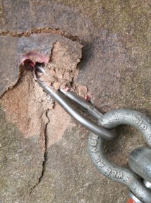
For those of the “ a few angle grinder cuts in the legs will do” school of thought here is a photograph of one of two bolts recovered after being ripped on a sport route in Hollental, Germany. The climber fell on the bolt after a hold broke, ripped it and the next and decked suffering severe injuries. The accident was reconstructed and the load calculated at 5 to 7kN. The glue was analysed and found to be fully cured and satisfactory but you can see for yourself how well it stuck to the bolt!
(Taken from “Hakenausbrüche beim Klettern.” D Stopper. Leader Safety Research, Deutsche Alpine Verein. First published in “Panorama” April 2001)
Eye.
The requirements of the EN/UIAA standards call for minimums which represent the familiar „Petzl“ bolt hanger, but these are the minimum. When designing my bolts I looked at real world climbing and designed the eye to make climbing safer and more convenient.
Our belay bolt eyes are large enough to allow a bight of rope to be pulled throught and attatched to the harness before untieing the rope end, a single figure-of-eight knot may also be passed through the eye when threading to lower-off . A major problem with many bent rod protection bolts is that if the quickdraw is pulled above the bolt the gate will be forced open by the upper leg, I therefore rounded the back the eye to reduce the potential of this occuring.
The minimum dimensions for the eye are given in the EN/UIAA norms, unfortunatly they seem to be a little outdated as the modern generation of karabiner with a forged “T” profile take up so much room that it is hard to fit a second karabiner in the eye. The Salewa manufactured Bühler bolt is a particular offender in this respect, some of the older Petzl hangers also can be annoying, the only solution being to carry some quickdraws with older bent wire karabiners.
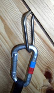
For makers of bolts the solution would appear to be making the eye larger but very quickly the problem of involuntary unclipping raises its head. As the climber passes the bolt rope drag tends to lift the quickdraw and the effect illustrated below can occur (and has, with fatal results).
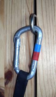
As one can see the lifting action of the quickdraw causes it to unclip, in this case in a simulated staple with a leg spacing of 35mm.
To reduce this effect the leg spacing or eye diameter must be kept down to around 15mm which rather precludes fitting a second karabiner or double-threading the rope in order to lower-off.
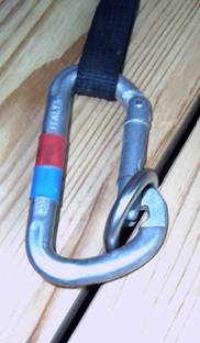
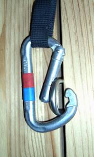
Another approach, which I used, is to increase the eye size to the extent that the the karabiner cannot unclip, the legs or eye needs to be about 60mm across for this to function as illustrated below. This eye size has several other benefits, if the climber grabs hold of the bolt they can insert 3 fingers into it reducing the likelyhood of severe injury if they fall, in addition if it nescessary to retreat from a route the rope can be threaded through doubled to clip into the harness before untieing, an obvious safety point. The only objection to this type of eye is an aesthetic one but they are no more intrusive than a typical plate hanger and a lot less than a dead climber at the bottom of a climb!
A third way to prevent unclipping would be to manufacture a bolt with more than one small eyes but I know of no bolts so produced, some Bühler bolts were produced with a bar welded across to achieve this effect but doubts about the action of welding on the integrity of the bolt led to this being dropped, most climbers were observed to clip the larger upper portion anyway rather negating the effect.
Other sections of the norms regarding the eye concern themselves with material thickness and edge radii to prevent karabiner damage, none of which present any difficulties with the types of bolt described here.
Practicalities.
While no doubt the aircraft industry could design „the perfect bolt“ we couldn´t pay for it, and if the rail industry designed it we certainly couldn´t pick it up so some elements of realism have to be considered, while for instance I think staples are a shocking idea (see under) full credit to the lads for putting them in, at least the routes are there and nobody has died.
Unless the bolts are to be paid for by general climbing funds instead of by a few dedicated climbers the following should be considered.
Material cost.- 8mm stainless steel costs nearly double the price of 6mm.
Manufacturing costs.- If bolt design becomes too complicated then only major manufacturers can afford the tooling and the price is correspondingly high, ergo less routes.
Ease of use-. Easier clipping, convenient retreat after failure on a route, easy threading are the benefits of a well designed bolt, none of which can be said for the Petzl style hanger.
Hole required.- In other words how many bolts can I fit from a charged battery. The requirement for around 3000mm² gluing area means whether I drill 10, 12 or16mm dia the rock removal will be the same BUT using 8mm stainless, i.e. drilling a 16mm hole, means the hole is too shallow and to get the required depth (80mm) I would have to drill twice as much hole.
Rock strength.- The advantage of Bühler bolts is that it is easy to adjust the manufacturing process to make longer bolts if needed for softer rocks, my bending jigs allow bolts of infinite length to be made.
Durability.- The life expectancy of the bolts themselves must be almost indefinate, the glue systems generally used have a life of at least 20yrs as long as they are compatible with the acidity values of the rock. Some problems have occured in humid climates and also in some sandstone types, there is information available on this from the D.A.V. which I will try to obtain. Important is to use glues designed for the construction industry as they try to make them ph neutral, problems have occured using other glues. Some advice from an idustrial adhesives expert would be welcome. The biggest problem with durability experienced in Germany with 6mm rod bolts has been the climbers repeatedly top-rope (nowdays called bottom roping I believe) routes with the rope threaded through instead of using a karabiner, over the years they wear very thin due to sand in the ropes.
![]()
Chemically Fastened Anchors. (Glue-In´s).
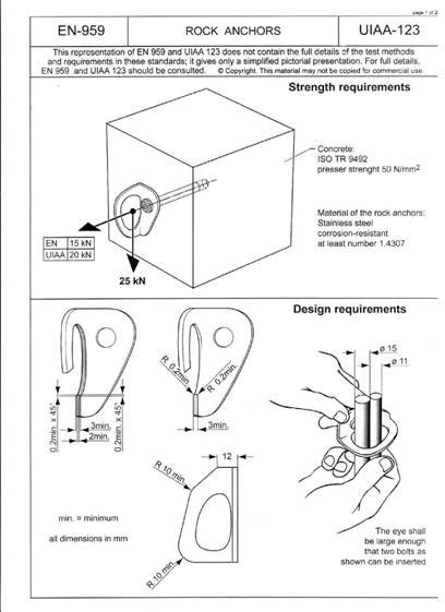
The current European standards relating to the manufacture and sale of rock anchors for climber protection are EN 959 and UIAA 123. The EN requires an extraction resistance (direct pull out) of 15kN, the UIAA 20kN. The radial loads (downwards in normal application) are 25kN for both standards. A pictorial representation of these standards is shown below, for copyright reasons it is not possible to give the full text.
Bolt Types.
Currently there are three main types of glue-in bolts in use. All are manufactured of stainless steel to conform to the corrosion requirements, the usual material being AISI 304 (A2)
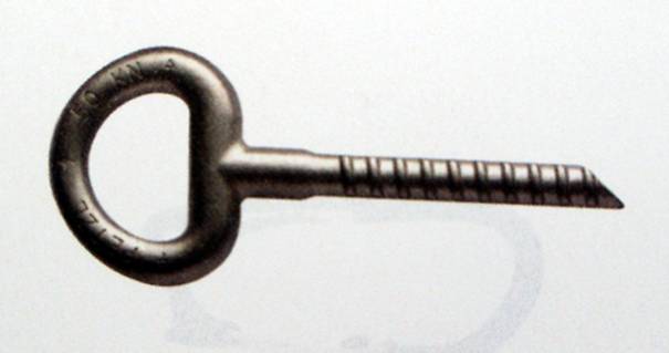
Forged Eye Bolt.
Various manufacturers, the one shown is a Petzl Collinox, the smaller of the two models they make and a fine product. 10mm dia shank grooved for better adhesion. Expensive forging tools put the price out of reach for equipping a large number of climbs, at €12.90 a go + €1.75 for the glue ampoule I doubt you will be clipping many of these. The larger Batínox for soft rock comes out at €23.90 + €3.50 for the glue!
There have been a number of welded eye bolts on the market but weld failures have always been seen as a problem. under 10kN. Another recent investigation by the DAV on a series of home-made bolts found eye failures as low as 50N! This was due to using the wrong grade of stainless steel, one intended for machining not welding. Another potential cause for failure is not controlling the weld cooling time sufficiently.
Welded bolts can and are perfectly satisfatory so long as the correct materials and procedures are followed so make sure they are from a reputable manufacturer!
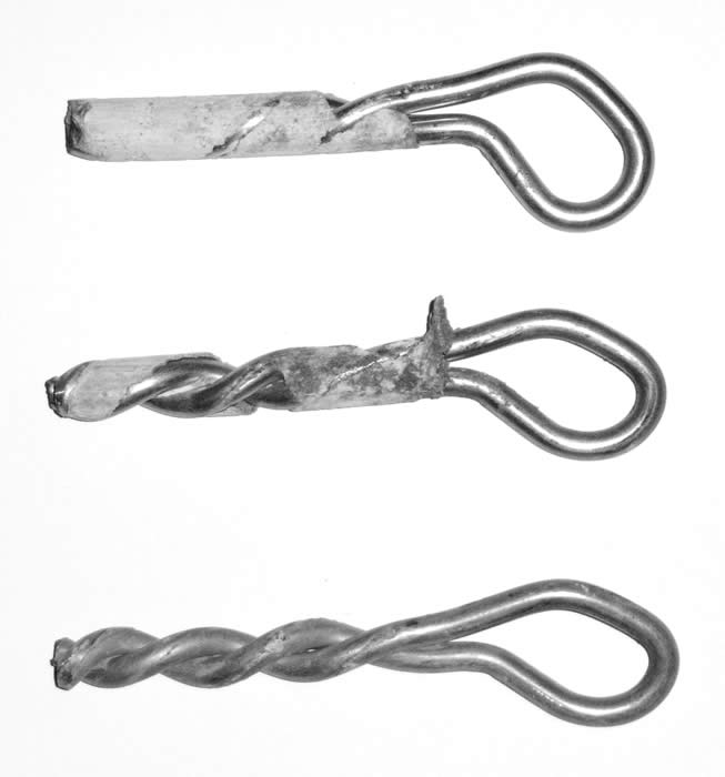
The Bühler Bolt.
Developed by the late Georg Bühler, a well known pioneer climber and engineer from the Frankenjura in Germany. Problems with the staples previously used led him to design this bolt for easy home manufacture and they are universal in the German speaking climbing world. The best bolt for home constuction and a big advantage is that it is simple to extend the leg length to suit soft rock. Either from 6 or 8mm dia stainless steel rod. (the 6mm rod can have wear problems if used for lower-offs but otherwise is easily strong enough). Usually 80mm long legs for limestone and up to 150mm for sandstone.
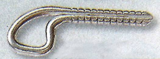
Shown is a home made bolt with a particularly large eye made from 6mm stainless. Note the large and rough weld, this is needed to provide resistance to extraction as the glues adhere very poorly to stainless steel. Material costs ca €0.40.
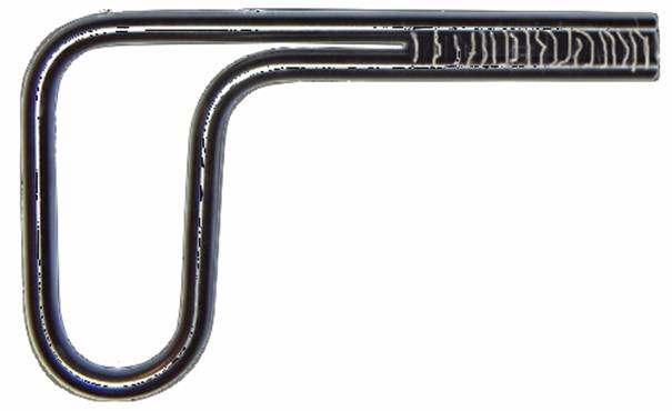
This is a commercially made bolt (from Austrian Alpine) using 8mm rod forged down to give a 12mm shaft with teeth to provide adhesion. Cost €4.95 + glue. Note the curved shape of the upper part of the eye introduced to reduce the chance of involountery unclipping.( see below)
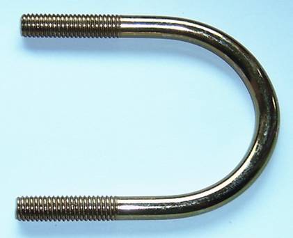
The Staple or U Bolt.
You may or may not be aware that these were in common use in Germany for many years. The Germans being thorough chaps go around testing bolts at regular intervals and the results led to two decisions. 1) To remove all staples immediatly as none achieved the required test figures. 2) To recommend the removal/changing of all bolt-in bolts after 10 yrs, all new bolt-ins should be sealed against water ingress, either as in the construction industry with a rubber ring, or with a silicon sealant, and to discourage the use of bolt-ins in areas subject to freeze/thaw conditions.
The test results for staples were not published by the DAV as far as I know but we made and tested some. 8mm dia rod with 80mm legs achieved around 6 to 8 kN, When I knurled the legs to improve the bond the rock failed, generally at around 12kN. Examination of the failure showed that drilling two holes so close together seriously weakens the rock, according to friends in the quarry industry the drilling produces micro-fractures and these link up producing an area of shattered rock between the holes. (A similar effect to when you try to fit a expansion plug in a masonary wall near to an old one). Another problem we noticed was that on the bolts with bonding failure only one leg failed, implying that the load is not evenly shared, therefore the bonding for each leg must be capable of withstanding the proof load.
This is one with threaded legs for better adhesion and extremely wide leg spacing I made up for testing some years ago.
Welded Eye Bolt
Usually threaded on the shank to provide a good bond this is a traditional design which comes in and out of popularity. While a number of these have proved to be reliable there are two areas of concern. The first and main one is the welding, without correct material selection and a very experienced welder this will always be a weak point, with too rapid cooling of the weld area leading to cracking and failure of the shaft itself. One on the market (not in Europe) that I know of is the USHBA bolt made from titanium, in tests by the German Alpine Association (D.A.V.) three out of five broke at the weld at under 10kN. The DAV have tested a large number of a home-made series and had shaft failures as low as 50N, the cause being the wrong grade of stainless steel! A secondary problem can be poor shaft preparation leading to insufficient bonding- the test mentioned here was performed after the death of an abseiler due to this very reason, the bolt pulling out under a load of ca 100kg.
Of course a well engineered bolt constructed by trained personnel won´t have these problems, the welded eye bolt from Fixe for example being an excellent product.
Here is the welded eye 12mm bolt from Bolt Products where you can clearly see the tidy weld correctly burnt into the shaft and the triple start machined grooves we use for exceptional bonding.
A fourth kind of anchor is available, basically a threaded bar but as this requires a hanger as well has not proved popular with climbers, it is easier to use a normal bolt-in.
For and Against Glue-in bolts.
For. Strong. Durable. Thief proof. Smooth eyes allow safe rope threading for retreat. No corrosion due to dissimilar metals.
Against. Usually require larger hole than a bolt-in. Akward to fit on very steep climbs except those from Bolt Products. Cannot be placed on lead. Messy, complicated gluing procedure. Need correct temperature for glue cure.
![]()
Glueing.
Regrettably not as simple as many would think. Various adhesives derived from the construction industry have been used; polyester, vinylester, epoxy , epoxy acrylate and, while not strictly an adhesive, quick setting cement.
One problem is that the manufacturers often do not write on the packaging exactly what the glue is and sometimes it takes a lot of research to actually find out, a good indicator is however the price as epoxies are usually at least twice the price of the others, currently around €28 per 300ml tube.
Most climbers nowadays are using vinylester/polyester due to its price and convenience, while not so strong as epoxy the mechanical nature of the “gluing” rather than adhesion and rock failure make this not so important as long as the bolt design is adequate. We have tested many bolts with these adhesives with satisfactory results. I fitted around 2500 bolts in Greece using epoxy for practical reasons and all my earlier test data is with epoxies.
If you are using a commercially available bolt you should note that the glue is an essential part of the test and certification process and you should only use the glue specified by the manufacturer.
Glue Types
Chemical anchoring adhesive systems come in a wide variety of ‘one shot’ products. (While not strictly speaking functioning as adhesives I will still refer to them as such.)
These products are suitable for fixing wall ties, starter bars, studs, large screws and bolts into a range of substrates such as concrete, brickwork, masonry, stone and PFA blocks. Once cured they form a tough, chemical resistant, stress free fixing making them ideal for ‘close-to-edge’ fixings – a major advantage over traditional expansion bolts.
Anchoring systems are available in various formulas designed to meet the needs of the construction industry and vary from manufacturer to manufacturer and the specification of the adhesive you use may be different to the one the bolt manufacturer tested with.
Styrene Based Polyester
A high quality, rapid curing resin anchor for small to medium sized fixings.
Polyester is normally used in cartridges, usually 310ml or 380ml with mixing nozzles though other sizes are available. The cartridges can be coaxial with the hardener in a central tube surrounded by the resin, or piggy back with one over the other. Both of these systems require purpose built guns.
Unfortunatly the mixed glue in the nozzles hardens within a few minutes so the routes must be prepared (drilled and cleaned) and then bolted in one go, carrying a spare nozzle or two is a good idea!
In the "good old days" bolt were glued with polyester body filler, a fumble with tins and hardener halfway up a rope!
On a cool day in the U.K. the normal speed resins give acceptable working time to jumar, place the bolt and move on to the next but in warmer climates or on a rare hot day the setting speed can make life difficult and a slower setting time is desirable. Storing the glue in a cool place is a great help, we sometimes use a cool bag and packs for this.
We are currently getting about 30 to 35 bolts per 380ml cartridge using 80mm long Bühler bolts and a 12mm hole giving a glue cost of around €0.30 to €0.40 per bolt.
Styrene Free Polyester
Similar in performance to the styrene based product, but having the advantages of low odour and high flash point, making it suitable for confined or sensitive areas, hardly relevant to us!
Modified Epoxy Acrylate
Improved chemical resistance compared to the styrene based and styrene free systems.
This is not a replacement for epoxy resin if this is the glue recommended by the bolt manufacturer.
Epoxyacrylate is marginally stronger than vinylester and its perfomance falls well short of that of pure epoxies, achieving less than 60% of the pull out resistance. Its main benefit for the construction industry apart from chemical resistance is its very low shrinkage rate which is a major problem in large diameter holes. Some formulations have better cold weather performance and the hardening appears to be faster than for the polyesters though this seems to vary from brand to brand. The water resistance of these glues is far better than that of epoxy making them a good choice for damp areas.
.
Vinyl Ester
A pure vinyl ester resin based system, offering the advantages of a fast curing system with exceptional chemical resistance and fire resistance.
Vinylester has no real benefits for us apart from being about 18% stronger, it´s main advantage over polyester is chemical resistance and fire resistance which are hopefully is irrelevant.
Vinylester is however commonly used by climbers, albeit often inadvertantly. The vast majority of glass ampoules on the market contain vinylesters such as those from Fischer/Upat and those supplied by Fixe amongst others, although most of the bolters I know think they are using epoxy. The confusion extends even to some major retailers who confuse the products.
Epoxy repair putty. By this I mean the pre-packaged little rolls of epoxy which you cut off and knead until mixed and use for repairing water pipes and such.
Usually comes in ca 60g packages. This could be convenient way of gluing one or two bolts without carrying cartridges and guns about.
I have tested two brands of this, one from Pattex (Henkel) commonly sold in Germany and another called Wetseal from Acrypol which is available in the U.K. The Pattex one doesn´t actually say what it is and proved to be not very strong, actually it gave the worst result of any glue I have ever tried. The Wetseal actually said it was epoxy and was twice as good with a one hour cure achieving respectable results (38kN) with our standard bolt test. The problem appears to be that for repair purposes a certain amount of flexibility is required and this reduces the putty´s load bearing capabilities, they are noticibly rubbery when cured.
This is a pretty pricy way of gluing but would be an option for that odd bolt.
Pure Epoxy
A superior system with all the advantages of epoxy resins, outstanding adhesive properties, no shrinkage - making it ideal for large sized fixings, low odour and excellent chemical resistance.
Epoxy adhesives are readily available in three forms;- bulk, self mixing cartridge and glass/plastic ampoules.
Bulk has the advantage of cheapness and guaranteed mixing quality but injection into the hole and working time can be problematic, I mixed batches of around 300 ml (depending on the number of bolts to be glued) and used a grease gun to inject it in the holes, due to the high temperatures in Greece (+35°C) it was an advantage to keep the epoxy cool with ice packs before mixing allowing a working time of about 30 minutes. For large numbers of routes on a sport crag it is the best way but takes some organising. ( I have fitted around 2500 bolts this way).
Cartridges are the choice of most climbers but are about threee times the price as bulk and the cartridge guns can be very expensive to buy along with the mixing nozzles. Ampoules, whether glass or plastic are could be the most convenient way and are therefore the most expensive, problems arise when they are not compatible with the bolt design, most requiring the bolt to be rotated rapidly to mix the glue correctly which is not usually practible. Most of the glues in ampoules is far too liquid for rock at any angle and I personally don´t use them.
You should note that there two types of ampoule epoxy glue. One only requires the bolt is rotated to mix the glue thoroughly, the other formulation must be rotated at considerable speed to heat the resin and start the cure, naturally totally impractical for climbers.
Quick Setting Cement
The most economical way to fix anchors but with some practical disadvantages. Probably the most durable long term method.
Commoner than one might think with widespread use before conveniently packaged polyesters became available and still used by some. It has two main disadvantages- it is a fiddly job mixing the cement and getting it in the hole while hanging from a rope and it is very slow to achieve full cure, 28 days being the norm. (That said, I have fallen onto a bolt using this after only 24hrs and it held). The advantages are it is very cheap, you mix for each hole so it is suitable for one-offs, you can buy it almost anywhere and need no special pistol and nozzles.
It´s durability is excellent, like most cement products it gets harder the older it is.
Under no cicumstances should you use this for gluing commercially available bolts without prior testing. We have of course tested Bolt Products twisted leg bolts with quick setting cement and easily achieve the European Norm after 6 days cure.
Others.
The adhesives from Hilti are variously hybrid urethane/methacrylate (HIT HY 150), hybrid/epoxy urethane (HIT RE500) vinylester (HIT C 100) and for the plastic cartridge (ampoule) system no data is given.
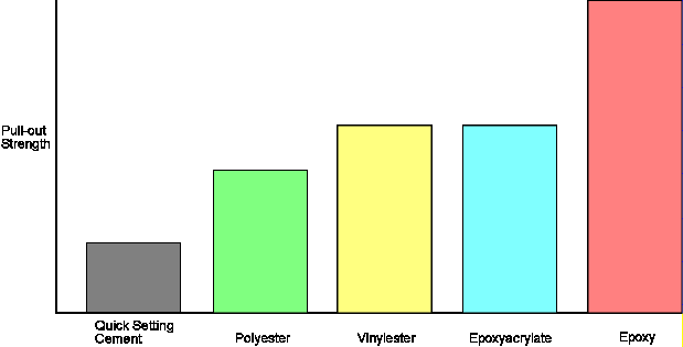
Typical relative pull-out strengths of anchor adhesive systems.
Successful Gluing.
The main factors are cleanliness, correct mixing, distribution, temperature and glue line.
Cleaning- obviously the bolt should be clean but due to the mechanical nature of the joint (see details in the bolt design section) this is not as critical as hole cleanliness. The hole should be blown and brushed out several times and dry, damp and dusty holes can cause a loss of up to 90% of strength, contrary to the advice by one manufacturer we follow the advice of others and use steel brushes for hole cleaning, enlarging the hole in most of the rock we bolt is not an issue and in fact widening the hole internally would be of considerable benefit! Damp holes are very hard to clean of all the drill residue and a good idea when applying the glue is to rub the nozzle against the sides of the hole to mix it into the resin. Most studies show a reduction in bond strength with damp holes, the extent varying with the type of glue and glue system. The vinylester cartridge system is reported to be unnafected in these circumstances, most likely due to the energetic spinning required mixing any water and debris into the resin and epoxyacrylate also being less affected.
Correct mixing should be a matter for the designers of the mixing nozzles if one is using the normal cartridge system but experience from other climbers has shown that a bit of help can be needed, stirring the glue in the hole with a thin metal rod seems to be the best way. A careful eye has to be kept on the nozzles to check they have not got blocked causing the wrong proportions of glue/hardener to be delivered. With ampoules care has to be taken to follow the manufacturers instructions on any nescessary rotation required to achieve adequate mixing. Using bulk epoxy one has the advantage of being able to control the mixing process exactly and one always has a sample of the last batch in the mixing container to check that it is cured. Unfortunatly the mixing can only practicably be done at the foot/top of the climb.
Distribution means that the glue should contact all the surfaces of both hole and bolt, as the hole is normally partially filled with glue from the bottom to prevent air bubbles and the bolt inserted there are two ways to ensure complete coverage, either design the bolt with channels or grooves to force even distribution or to rotate the bolt as it is inserted, most commercial chemical fasteners call for rotation using an electric drill to ensure correct distribution and mixing. This is one failing of the staple as it cannot be rotated and in tests large air bubbles have been found on the shafts with obvious implications for their strength.
Temperature is not normally a problem in that most construction adhesives are designed to be used at normal building site temperatures which are the ones at which most climbers are active. So long one is in the temperature range specified then all is good except that when it is cold full cure can take a very long time, epoxy<acrylate seems to be better in these conditions. High temperatures mean that working times are short and more mixing nozzles may be required but I have bolted for many years in temperatures up to 40°c without difficulties apart from the need to be well organised due to the short working time, one can to advantage condition (cool) the resin beforehand but better is to obtain a resin designed for higher temperatures.
It is important that the glue does not get too cold (i.e. near freezing) before curing as this stops the reaction!
Glue Line-or better described by some authorities as Critical Glue Mass, is often overlooked but is very important (I have tried to simplify this to make it easier to understand).
Epoxies and esters are exothermic, that is they require heat to cure and therefore they rely on the fact that they can raise their temperature (normally to ca 65°c) faster than this heat is conducted away by their surroundings. Placing a relatively large metal bar in the glue is obviously not the ideal situation as it will conduct the heat away and prevent full cure, for this reason most manufacturers call for a hole 2mm larger than the object to allow a thick enough glue line or glue mass and therefore an adequate heat build up and cure. Interestingly this effect was also discovered in the early 80´s in the timber industy and they also recommend a 1mm glue line when embedding metel fasteners.
A problem is then to ensure the glued object is in the centre of the hole, commercially this is done by various methods, the most obvious is the perforated plastic sleeve often supplied with chemical fasteners for hollow blocks but impractical for our purposes. Another way is to supply the glue in a glass cartridge which is designed to break up and act as a spacer/filler, a third way is to give the bolt a shape in which parts of the bolt are large enough to centralise while the rest is left for the glue, typically this is the approach used by Bühler bolts and by the newest Hilti chemical anchors. The illustration of the Petzl bolt above shows this clearly, the neck of the shaft is larger than the rest, they are also supplied with glass ampoules.
We have sufficient glue mass in the twist of the legs on our bolts and do not require a smaller hole to be drilled.
Cure Time
The cure time varies depending on the glue type, temperature and formulation, most construction glues have a cure time of around 1-3 hours but the epoxies usually achieve their full strength after a longer period. I tested a steel-setting epoxy with a stated cure time of 7 days at around 20°C by placing 7 bolts and testing one every 24 hours, after 24 hrs the bolt failed at 12kN, 48 hrs – 22kN and it took 3 days to achieve full strength 38kN (rock failure).
The graph below shows the relative curing times for various anchor bonding systems (full cure) the epoxy being of a particularly fast type. The hatched areas are the initial setting (gel) time.
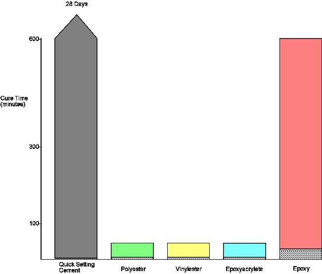
The polyester, vinylester and epoxyacrylate are faster as you can see, with most manufacturers giving identical times for the various products, though this is probably not exactly so.
Of interest to us is how soon can we safely load the anchor and for this we need a curve of strength against time. For polyester, vinylester and epoxyacrylate there is a good rule of thumb which says that they achieve 80% of their final strength after 4X the gel (initial set) time. We have performed a series test for this and the results can be seen below, along with a composite curve from various manufacturers test data and the curves for 4X from various gel times. As you can see the 4X times rule is a little conservative but it´s better to err on the safe side.
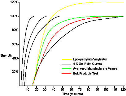
The lower curves to100% are for polyester, the upper is for epoxyacrylate and vinylester and uses extrapolated manufacturers data. We attempted a series test of epoxyacrylate but the first pull 20 minutes after gel resulted in the bolt breaking at 4820kN. A look at the graph shows us that the test time of 35 minutes should give a value of around 95% which on this graph represents 4900kN so obviously this was correct.
We have also axially tested quick setting cement with values obtained:- 1 day 8,6kN
6 days 19,2kN
28 days 35,4kN
but note these values are for a Bolt Products bolt which would have achieved 8kN tested without any adhesive.
If you use this information to decide when it is safe to climb then note that the values are in % of the strength, if the bolt is only marginally over the required pull-out resistance when the resin is fully cured then be careful!
Edge Effect.
If a bolt is placed too near the edge of the piece of rock or near a crack/fault the loading of the bolt will cause the rock to break out in this direction at a relatively low load. There has been much research into this and the general recommendation is not to place a bolt within 200mm of the edge, some go as far as 400mm. Unfortunatly when using the staple type of bolt the action of drilling a second hole creates this edge and the cones of failure overlap, seriously reducing the load bearing capability. The fastener company Hilti recommend a hole spacing of twice the hole depth for adjacent fasteners to avoid this problem. ITW Ramset give a hole spacing of 1.5 x depth as the critical spacing and a distance of 1.25 x depth from an edge. The UIAA recommend a spacing of at least 200mm when fitting two bolts at a belay.
![]()
Long Term Durability.
The general concensus seems to be that glued-in bolts have an almost indefinate life span. The D.A.V. tested some older bolts (up to 15yrs) and found no loss in strength.
The glues themselves when cured are chemically inert and should not degrade though some weakening from water has been observed with polyester. Additionally they often contain cement powder as a filler which provides an additional long term fixing. The glues used in the construction industry have an expected life span of at least 20yrs and the European standard for chemical anchors gives a life of 50 years as a reference point for designers.
A2 stainless steel has proved to be a reliable material in the marine environment and it is hard to foresee any real improvement to be made, A4 being rather more difficult to work and more prone to work hardening.
The main problem with durability has been climbers persistently top-toping threaded directly through the bolt, depending on the area and use after 10 to 15yrs they get pretty thin! The only cure for this is much thicker bolts at the lower off or the use of loose rings, I personally manufacture my lower-offs from 12mm bar for this reason and also for smoother rope running.
An interesting point was raised on a recent UKClimbing forum was about the difficulty of recording and tracking the date and details of bolts fitted in order to perform constructive long term testing. The climbing committee in the Elbe sandstone region of Germany has been carefully logging every bolt fitted for over one hundred years in the largest climbing area in the world with around 20,000 routes without the benefit of computers, surely it should be possible generally to do this nowadays in order to establish some kind of database?
There has been some debate about bolt durability at coastal locations and the UIAA are considering a new standard for this, an article published by the UIAA in 2000 discusses this but does not give details of glued-in stainless bolts, the concerns appear to be regarding stress corrosion cracking in bolt-ins, a phenomenon not unknown in the marine industy. As long as the bend radii in the bolt are relatively large this should not present a problem for most of the glue-ins I have seen as they are not under permanant stress.
The latest version (06/2007) of EN959 has adressed the issue of durability, both in normal conditions and in sea water environments. Unfortunately the standard is of no real help, neither defining durability, nor the conditions so manufacturers are left to write the usual disclaimer including plenty of "possibly", may" etc. The situation regarding sea water bolts is even more ludicrous without even a definition of what defines "coastal", engineers working with stainless steel are quite used to designing or specifying material depending on the chloride (salt) concentration in air or water and can make sea water resistant bolts but as the standard is at the moment you may use any material and just say life may be limited.
Long term load tests.
There has been extensive research in the construction industry on the effects of long term continuous loading ( Meszaros/Lehr for example) but rock anchors for climbers are not usually under this type of load. However the fact that the tested anchors have withstood 50% of their breaking loads for test periods of years gives one confidence in their life span. Polyester displays some creep especially when damp and under freeze/thaw conditions and a better choice would be vinylester or epoxyacrylate if these are to be expected.
Repeated high loads are a concern for many who consider that repeated leader falls will weaken the bolt. We know of no other manufacturer who has published cyclic load tests on anchors for climbers but we have put a bolt through 1000 rapid cycles of 0-25kN axial loading, then increased the peak by 5kN at a time for 100 cycles each until ultimately the block failed at 44,6kN.
Lower-Offs
A difficult subject with many solutions being used in the past.
For myself and most climbers I know a lower-off needs to be strong, easy to use, safe and durable.
Strength- The UIAA allow lower-offs to be weaker than normal bolts, the reasoning being that they are not subject to leader falls, however climbers do strange things and I have seen leader falls on lower-offs. My thinking is that they should be as strong as belay bolts and can then be used on multi-pitch routes as belay/abseil points as well, basically my feeling is everything I fit in the rock must hold 25kN as I have no control over its later use.
Easy to use- Preferably one handed.
Safe- There two aspects to be considered here; a) fitting the rope in without endangering the climber, and b) the rope remains in place no matter what the climber does later.
Either the climber threads through or clips/ hangs the rope in.
a) For threading through the eye should preferably be large enough so that a bight of rope can be pushed through and knotted, to be clipped with a screwgate to the belay loop of the harness before untieing the end, thus the climber is never detatched from the rope. (One reason I make my bolt eyes so large).
Clipping or hanging the rope in is faster and easier but can lead to plenty of problems as discussed below.
b) The UIAA standard requires that to remove the rope from the lower-off the climber must move part of it, the implication being that some sort of clip or sleeve is used, unfortunately in the real world these moving parts become immovable or damaged as anyone who has struggled with seized up old krabs at the top will know. Most of the lower-off s designed in this way , even if in good condition, have the problem that either by climbing above and falling or because of whiplash in the rope can allow the rope to become unclipped. I use another approach similar to the pigs-tail system but stronger and safer,which has no moving parts and ensures that when in place the rope cannot come out no matter what happens. With this design the complete lower-off is a one-piece glued in fitting without the attendant problems of welding. Being made of 12mm bar they are immensly strong and rope wear and damage is not an issue, they are also able to be made without specialised tooling and are therefore financially within the reach of most bolters.
Durability- After many years of use wear from the rope, and particularly grit in the rope, causes a groove in the lower-off eventually weakening it, especially if the route sees a lot of top-rope activity. One way to prevent this is using a loose ring which should rotate and therefore distribute the wear. The approach I favour is to make the lower-off so massive that weakening will not be a problem in the lifespan of the bolt (over 20yrs?), therefore I use 12mm rod for lower-offs.
Calculating Bolt Strength.
Requirements.
In Europe the sale of rock anchors for climbers is controlled by the E.U. and the anchors are required to conform to EN-959. This calls for a direct (axial) pull-out resistance of 15kN and in the direction of fall (radial) 25kN in concrete with a compressive strength of 50N/mm².
A higher standard is required to satisfy the U.I.A.A. who call for 20kN axial and 25kN radial.
At Bolt Products we realise we have no control over the orientation of the installed bolt or the load and we set our our own standard at 25kN in all directions, in fact our internal standard is even higher than this and we would not offer a bolt which could not hold 30kN in any direction.
Failure.
There are three failure modes possible; bolt failure, rock failure and bolt/rock interface failureand we need to calculate the strength of the components to avoid bolt failure below the required loading, in our case 25kN.
Not all of the installation parameters such as rock quality and gluing can be strictly controlled so I generally prefer to add in a safety margin of 50% so ideally look for around 38kN.
Contrary to the expectations of many, no matter which way modern bolts are loaded the failure is in tension regardless of the load direction. The rock crushes under the bolt and it tries to slide out even when radially loaded, as can be seen in the following picture.
In the subsequent paragraphs the figures given are for axial pull-out.
Bolt Strength
This is the easiest to control as the manufacture of the material and subsequent bolt take place under controlled conditions.
The grades of stainless steel used for bolts AISI304 and 316 have a nominal tensile strength of 700N/mm² and 690N/mm² respectively.
The strength of the bolt will then be its cross sectional area in mm² multiplied by this, for example a typical M10 bolt-in has a minor thread stress area of 52,3mm² according to DIN, multiplied by 690 for 316 material we get 36,087 N or 36kN which is normally around the figure we achieve in testing (38kN).
In fact it is a pity the standards authorities picked 25kN, a little bit lower and we could use fine thread M8 bolts at 24.9kN!
If the bolt has two legs which become equally loaded such as a Bühler bolt then you can divide the required material between the legs. For one of our standard 6mm rod bolts we have 3² x 3.142 x 2 x 700 (304 material) which gives 39,6kN.
Interestingly we get test results of over 50kN which is due to the fact that when cold worked this grade of stainless becomes both harder and stronger,in fact we calculate it to be over 890N/mm².
(I have constructed prototye bolts using 4mm rod which achieved the standards for EN-959 but customer resistance is a problem!)
Rock Strength.
In many ways this is the difficult one, but as you will later see is of lower priority than interface strength.
Rock is generally not a homogenous substance, it can have cracks, inclusions, pockets and built in stresses which can effect its strength so you really want a good margin of error here. Tests in concrete show that there is a relationship between rock failure and compressive strength, although this is not linear in the dimensions we work at it is assumed to be so, and break out can be calculated using the projected area of the cone of failure.
The American Concrete Institute (ACI) give the following formula for calculating the concrete load bearing capacity:-
P = 0,32(Ac)x sq.rt
Fc
where
P = concrete capacity (N)
Fc = material compressive strength (N/mm²)
Ac = pi(hef)²
hef = anchor embedment depth (mm)
And so, using our bolt in again in a test block with a compressive strength of 40N/mm² and an effective embedment of 70mm we get;
Ac = (3.142 x 70)² = 48374
piFc = 6,32455
Put into the above we get P = 0,32 x 48374 x 6,32455
= 97902N or 97,9kN
One would think this was plenty strong enough but as pointed out above the rock at your local cliff may well not be completely homogenous, and of course its compressive strength may not be 40N/mm². While this value is actually quite low for the rock most of us are used to there are plenty of areas where climbers are active on rocks weaker than this, many sandstones testing at 27N/mm² or so and I have a customer bolting rock of under 10N/mm² .
Any one of a mathematical bent will also have noted that in the formula the length factor is squared and so the length/strength relationship will be a logarithmic one. We can see this by reducing the embedment in the above example by one half to 35mm which gives a strength of 24.47kN or one quarter of the previous result.
The conclusion to draw from all this is that while all may seem well if you start to reduce bolt depth as well as placing in weak rock and throw in a few imperfections in the rock structure as well you soon get to a situation where rock failure becomes a problem. Luckily the solution is fairly easy, use longer bolts and try to find sound, homogenous rock for placements.
The EN standard test block has a compressive strength of 50N/mm² and this is, by rock standards medium to low. Here is a table of the range of strengths for typical rock types.
Unconfined compressive strength:-
Granite 100-250 N/mm²
Basalt 100-300 N/mm²
Quartzite 150-300 N/mm²
Sandstone 20-170 N/mm²
Shale 5-100 N/mm²
Limestone 30-250 N/mm²
Marble 100-250N/mm²
Slate 100-200 N/mm²
Quartzite 150-300 N/mm²
Concrete 14-42 N/mm²
High strength concrete 70 N/mm²
You will notice that sandstone, limestone and dolomite all can have values well below (and above) that of the norm. test block and if it is seriously low you need to think about longer bolts. At Bolt Products we offer protection bolts with 100mm length for soft rock and for very soft (10N/mm²)or so we supply 150mm ones. The lowest we have had tested is in rock of 7,14N/mm² (laboratory tested) which really is going to be about the bottom limit of climbabilty.
.
So how do you know how strong your local rock is?
Obviously the best way is to take a sample and have it tested, unfortunatly this costs money. However most areas with rock outcrops also have quarrying activity nearby on the same kind of rock and the quarries provide this information in their websites or catalogues for the building industry. The biggest problem is you may well find that rock to a quarryman will mean 20 different types with curious medieval sounding names so you may have to visit them personally to learn about the differences.
For instance the rock you climb on in the Isle of Purbeck. U.K. could be any of these quarried stones;
Spangle 98N/mm²
Freestone 86N/mm²
Cap 207N/mm²
Blue Marble 145N/mm²
Grub 150N/mm²
Thornback 120N/mm²
Inland Freestone 102N/mm²
Bowers Roach 44N/mm²
Bowers Basebed 55,5N/mm²
Bowers Whitbed 37,7N/mm²
Grove Whitbed 49,8N/mm²
Jordans Whitbed 47N/mm²
Fancy Beach Whitbed 47,0N/mm²
Jordans Basebed 41,2N/mm²
though mostly one is on the chert or the freestone above, or of course it could be something so soft and weak they don´t quarry it!
To get a rough guide to compressive strength you can use this standard geologists test.
Field test for compressive strength of soils and rocks
Extremely strong rock Only chipped by repeated blows >250N/mm²
Very strong rock Very hard rock, requires repeated hammer blows 100-250 N/mm²
Strong rock Hand specimen can be broken with single blow 50-100 N/mm²
Mod. strong rock 5 mm indentations with hammer pick end 12.5-50 N/mm²
Mod. weak rock Too hard to cut by hand with knife 5-12.5 N/mm²
Weak rock Crumbles with blows of pick end of hammer 1.25-5 N/mm²
Bolt/Rock Interface.
Either the mechanical action of the bolt or the adhesive power of the glue used has to transmit the load from the hopefully strong enough bolt to the rock.
Mechanical bolts are very hard to calculate and so the fastener industry, to reduce the amount of in-situ testing, have introduced the concept of "torque controlled" bolts. Amongst these are the familiar wedge or through bolts used by climbers and depend on the application of a pre-determined torque to check they will have sufficient extraction resistance. In effect every bolt is tested when it is fitted.
In areas with particularly weak rock in may be found that the required torque cannot be applied as the bolts pull through. Under load the bolts can either rip out through the rock, or more commonly, the rock crushes outwards under the pressure of the sleeve and allows it to slide off the end of the bolt.
A better choice for this situation are so called "undercut" bolts or glue-ins which will give vastly superior results.
Glue-ins are another story and you can to calculate the theoretical strength which, assuming you have provided sufficient keying to the bolt and the hole, depends on the adhesives strength, hole diameter and depth.
One formula (Uniform Bond Stress Model) for this is:
N = B(pi)(d)hef
where
N = bond strength (N)
B = bond stress for the adhesive (N/mm²)
pi = 3.142
d = hole diameter (mm)
hef = anchor embedment depth (mm)
(Manufactureres seen very reluctant to publish figures for the bond strength but most researchers for the construction industry give values of 5N/mm² for quick setting cement, 8-10N/mm² for polyester/vinylester and ca 15N/mm² for epoxy. For the product you wish to use you can normally reverse calculate the value from the ultimate pull-out strength tables that most suppliers publish.)
So glueing in a threaded bar the same as our bolt-in we would get;
N= 7 x 3.142 x 10 x 70 = 15395,8N or 15,4kN.
Nowhere near enough but you should note that not only have I used a low value for the adhesive (in this case the bottom limit for polyester) but also drilled the hole the same as the bar, not a good idea anyway for other reasons discussed in glueing.
If we go up to better quality polyester at 10N/mm² and a 12mm hole we get
N = 10 x 3.142 x 12 x 70 = 26393N or 26,4kN
Much better and of course if we used epoxy at 15N/mm² this should get up to around 39kN although in practical testing this 50% extra strength is rarely seen.
Of course most of the single stem 10mm bolts available are at least 80mm long for this very reason and some actually specify using epoxy, partly due to the difficulties in getting enough mechanical engagement in the bolt without seriously weakening it by cutting or pressing indentations.
Looking at the Bolt Products standard bolts and using the same formula and with polyester at 8N/mm² we get;
N = 8 x 3.142 x 12 x 80 =24130,56 N or 24 kN
which is fairly consistant with test results from other bolts of this dimension, but no-where near the actual test results we achieve as you will see below.
Bolt Products Glue-In Bolts.
You may have noticed that for our own glue-ins we give much better results than this, a minimum is 35kN and in reasonable rock we achieve around 50kN at which point the bolt breaks. In fact in an independant test a bolt was still holding 31,4kN when testing was stopped with only 42mm of embedment. The bolt was glued in using an epoxy rated at 12,4N/mm² in a 12,7mm (½") hole which with this depth should only hold to 20,78kN.
Obviously either the formula gives incorrect results or there is something special about our bolts.
The answer lies in the unique structure of Bolt Products bolts which allow us to use both mechanical and chemical fastening. Not only does the twisted leg design give outstanding mechanical keying for the glue but a wedging effect is induced internally in the bolt when you try to extract it. As the two legs are not joined at their lower end they slide across each other and wedge into place, roviding an additional mechanical effect along with the normal glue.
To demonstrate this action we have tested a number of bolts dry fitted without any glue.
The photographs and results below are from tests in a granite block until it disintegrated. We then moved to a softish concrete block and achieved an amazing 33,84kN with an 8mm rod bolt.
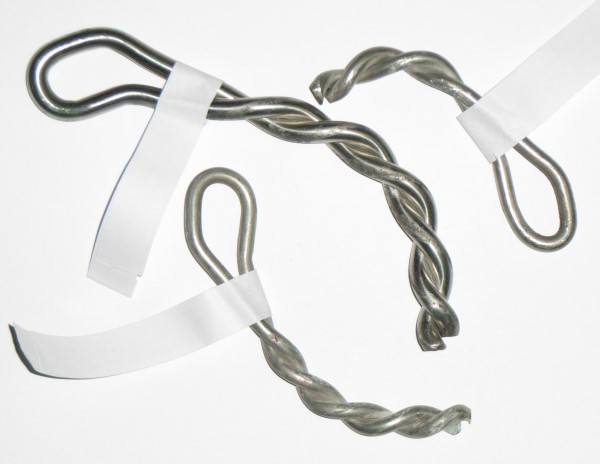
The bolt top right is a 6mm rod 80mm long bolt radially tested in a granite block to 19.8kN when it extracted.
The large bolt in the centre is a 8mm rod X 150mm long bolt radially tested in a soft concrete block which held 33,8kN.
The bolt lower left is a 6mm rod 100mm long bolt also tested in concrete to 18kN at failure.
Axial tests we have performed give values of around 60% of the radial tests.
![]()
Testing
Testing can be fun, is highly instructive and essential if you want to develop an anchor sysem but is also a brutal test of material and nerve. The test rig must be vastly overbuilt, most people who have built testers without a good `feel´for the forces involved end up with a lot of crumpled steel and a mk.11 or mk.111.
To clear up a common misconception;- rock anchors are designed to be used in conjunction with an energy absorbing element, in our case a climbing rope . This means they are static tested, not dynamic. The bolt itself cannot absorb energy, only transmit a force. The energy gained in a fall is absorbed by the rope and becomes a force on the anchor.
Terminology
The Newton (N) is the force required to accelerate an object weighing 1kg to a velocity of 1m/s. It is roughly the weight of 102g at sea level. To convert kg force to N multiply by 9,8 (more exactly 9.80665).
"Axial" testing refers to a test where the bolt is pulled directly outwards from the test object.
"Radial" is when the direction of pull is at right angles to the bolt, (downwards to a climber)
Testers.
Obviously in order to test bolts you need a tester, this has to be able to a)apply a sufficient force and measure it or b)apply known force.
Most commercial fastener testers used in the construction industry have a few drawbacks; they are expensive, are designed for flat concrete surfaces and have a limited travel so most people I know build their own.
Normally you want a tester that can be adjusted to be stable on rough rock, load to ca 7000kg and have a pulling distance of 150mm or more. And built very strongly!
The way I first tested was simple, I used a large fork lift to try to pull bolts out of a large boulder with a 55 ton crane parked on top, if I could break a doubled strand of climbing rope I was satisfied!
Naturally this presumes one has access to all of the above and is not really suitable for testing on the cliff, nor of course does it give very detailed measurements.
The next was a hydraulic car jack on an elevated base plate with a yoke to transmit the pull to the bolt below. To measure the force applied I welded a socket to the pivot of the pump side and used a torque wrench as handle. The first model was 4 ton but this soon succumbed to the pressures of life and the next was replaced by one with 7 tons and with a manometer to measure the force. Curously the torque wrench method turned out to be the more accurate at about +- 5%.
Currently we use a nominal ten ton press cylinder through a linkage to pull 20 tons using a remote pump (sometimes a bit more remote would be comforting!). This is pulling a Tranducer Technology load cell with a calibrated VMC Inc electronic strain guage accurate to 2kg over its range of 10,000kg which is also remote reading. You can get load cells with the display integrated but I doubt it would last long and I wouldn´t want to be that near to it anyway!
For loads over 10,000kg (don´t ask!) we use a calibrated manometer to measure the pressure and calculate the strain from this.
For radial testing I can mount this horizontally or I use a 5000kg pulling cylinder with the same load cell. Depending on the anticipated load we use two 16mm bolt-ins as the anchor.
For stretchy things like slings or for stakes which need a very long travel we use a 4000kg wire winch with the strain guage mounted between.
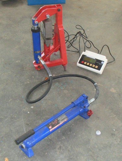
Obviously you want to join all this to the test object and the way to go is either very big shackles (cheap but heavy) or plates and hardened bolts. Shackles and maillons distort when they are highly loaded and cannot be undone afterwards, therefore they need to be big. 22mm or 25mm seem to be the size for loads up to about 7 tons.
The plate system shown below is probably the most convenient and adjustable system and the bolts are easily removed and changed when bent. I use 16mm bolts throughout except for the one through the object being tested, this is normally high tensile 10 or 12mm.
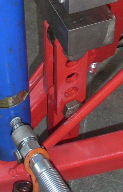
Forget maillons, old karabiners etc unless you get pleasure from breaking things. Most of the tests you read elsewhere say things like "we test pulled to XX kN" or "we stopped testing at Xx kN. This is normally a way of saying;"our tester broke"! The forces can be shockingly high, for instance I used to use single16mm dia lag bolts for holding the tester when radial testing but they broke at 5500kg so now it is either a single 20mm or two 16´s. We are supposed to test bolts using a 10mm pin to replicate a karabiner but at the loads on some of the bolts we produce we have to go up to hardened 12 or 16mm ones.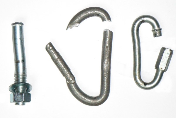
A collection of dead testing gear:- 16mm steel Fischer lag bolt (5650kg). Old and corroded aluminium Bonatti Krab (2700kg). Cheapo 10mm steel maillon (1920kg)
Tip.
When you go out shopping for any of this gear you should be aware that not everything inside the box is what you think it is.
For example:
4000kg rated winch- it doesn´t actually say you can pull this, they mean it can withstand this much. Neither I nor my brother could get over1100 kg and a bit of calculation shows that we would need to pull 266kg on the handle to achieve 4000! It now has a much longer handle.
10 ton pull cylinder- this is used on the same pump as it´s brother press cylinder. The press cylinder has an effective power ratio of 200:1 so 50kg on the handle gives 10,000kg at 690 bar (measured) whereas the pull cylinder, while rated the same, in reality only has a ratio of 100:1 so really it is only 5000kg .
And of course pumping with 50kg on the handle is hard work!
If in doubt buy bigger!
Testing.
DANGER- This can be dangerous, the loads on some pieces of gear can be very high and when they break pieces can fly around and cause a lot of damage. Try to stand well clear and out of line of the tester. If I think it´s going to be dangerous I place material/old jackets etc over the set up to catch the pieces. With glue-ins this is rarely a problem but bolt-ins fail explosively with bits flying everywhere. The tester will also move with recoil and you may need to restrain it.
If you use any elastic element in the set-up this can be extremely dangerous.
This includes slings and rope, and to a lesser extent wire rope and chain. Always fit restraint leashes if you use anything remotely stretchy and make them strong, (old climbing rope is ideal) especially when horizontal testing.
If you think I am being over cautious, the tree in my garden will always bear the scars of a 5kg load cell, a cable winch and assorted shackles slamming into it when an old rope we were testing finally let go at 1900kg.
Testing Protocol
An upmarket way of saying you decided what to test and how. Unless you have a specific need the EN decides how you are going to test and the protocol is written in the standard (which you will have to buy). Fundamentally this states the directions of pull, speed and fixing details as well as the test block specifications.
(Some people have tried to make a case for angled pull testing on the premise that this reflects a fall. This is naturally rubbish. I have fitted bolts into easy slabs and also inverted under roofs and cannot see how one can generalise about the loading angle. EN959 specifically requires axial and radial tests and all other intermediate values can be found using the formula to be found in ACI 318-02 Appendix D).
The axial test is generally the weakest and most testers only do this. If the bolts can withstand this "worst case" then passing the radial test will be easy.
It is however instructive to do some radial testing to see the mechanism of failure and incidentally to be amazed at how much this mangled metal and cracked rock is holding!
For development I normally test in batches of three but for certification I follow the lead of the construction industry and take a sample of five.
Multiple Load and Fatigue testing.
There is currently no requirement for this but humans are inquisitive.
High frequency testing. Partly because of questions about repeated lowering off and also vibration from strong wind (some people out there really are nervous!) I used a glue-in bolt as the anchor for the engine steady on a 250kW diesel generator. This was pre-loaded to 80kg and left to vibrate. I stopped looking after 130 million cycles.
Multiple load. Multiple load tests to replicate repeated falling may be introduced for manufacturers to achieve the UIAA standard and mooted is something like 10 X 10kN to represent repeated leader falls and must still be usable, then proof tested.
One of our bolts was independantly tested by deliberately incorrectly installing it (with the eye 10mm out from the rock) and then jerk loading it to 5.34kN 100 times and then proof tested. This bolt passed with flying colours as did the next which was correctly installed.
We have recently tested one of our 6mm rod, 80mm long glue-in bolts bolts for repeat high load falls as I felt the test above was a bit on the low side. The proposed UIAA standard was also felt to be on the low side so I axially tested (straight-out pull) to 25kN to see what happened. The load was applied through a load cell using a powered hydraulic ram, rising from 0kN to 25kN in less than 0,2 seconds, held for 2 seconds then released. This was repeated 1000 times with no sign of failure or movement after the initial loading of the bolt. The load was then increased to 30, 35 and 40kN for 100 cycles each. The test block then suffered from edge failure as I attempted to raise the load to 45kN.
This winter we will be trying some more ideas so watch this space.
![]()
Pitons
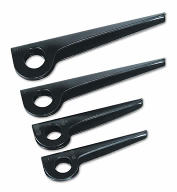
There is little or no research into piton holding power and strength to fall back on and so I performed over 100 test pulls on a variety of sizes and materials in soft and hard rock. Some of these test were performed outdoors in soft Frankenjura limestone with the help of Karsten Oelze who fortunately has (had) a large selection of pitons, these test being performed pulling straight out. The other tests were performed in granite blocks at my workshop and were arranged as downward pulls in a horizontal crack,
Pitons for sale in Europe are covered by EN569 and there is an additional volountary standard from the UIAA; UIAA122. It is clear that most manufacturers and retailers ignore these standards or provide no information to whether their products conform.
Reading the standards it it´s easy to see why, they are a curious collection of strength requirements which appear to have been picked out of a hat and have nothing to do with their holding power. Of course holding power is what we are interested in, an eye which withstands 25kN is not much use when the piton falls out under bodyweight.
EN569 has two categories of piton, Safety which are marked with an "S" and Other which are unmarked (some categorise these as "P") and these two types have different eye strength requirements. The standard requires the eye strength to be measured in three directions, down, up and sideways (the piton is mounted in a specified fixture for these tests). These strength values are all different for reasons I don´t understand.
The UIAA standard then has two further sub-categories of piton; soft and hard. These are respectively below HRC 22 (HB30=240) and above HRC 28 (HB30=240). One can only assume no one wanted to make or use a "medium"piton.
Some Myths
Myth 1:- Soft steel pitons are for permanent placements. Truthfully this should be "soft steel pitons WILL become permanent" because they are almost impossible to remove. Their performance is in all respects inferior to the other materials.
Myth 2.-Soft steel pitons mould themselves to the crack and hold better. Of course they mould themselves but this doesn´t help them stay in, once the initial friction is overcome they pull out under very little force. In all my tests the soft steel pitons were consistently the poorest by a cosiderable margin, bent or not.
Myth 3:- You drive a piton in until the pitch of the ringing stops rising. All the pitons I tested had different pitches of ringing, angles making a lovely sound even when not in a crack. Stopping driving early when the pitch appeared tobe at it´s highest gave easy to remove pitons, in fact what we considered `good´ turned out to be unable to even hold the initial weight of the tester. The maximum pull-out resistance was achieved when they were "beaten to death", either because we just couldn´t hit them any harder or they started to collapse. Of course ones ability to hear when the ringing stops rising could be age related anyway, beware of old mens pitons!
Myth 4:- Titanium is light, strong and corrosion resistant. Pure titanium is in fact quite weak and soft, ASTM grade 1 having a tensile strength of only 240N/mm². (`mild´ ASTM 1018 steel is 440N/mm² ). Alloyed with aluminium and vanadium (grade5 for instance) gives the highest tensile strength of 896N/mm², about the same as cold worked stainless steel and chrome-molybdenum. Unfortunately in this condition it is prone to stress corrosion cracking in the presence of salt so for sea cliffs one needs to add palladium, ruthenium or possibly nickel. A good choice for pitons would be something like grade 27, a `low´cost titanium/aluminium/vanadium/ruthenium alloy.
`Low cost´ is relative as ingot prices start in in the hundreds of thousands of dollars per ton and I would expect to be paying over €300,000 per ton for rolled material!
How Pitons Work
Pitons stay in the crack because of friction. In a straight out pull the force required to extract the piton is the same as the force required to insert it- friction works equally in both directions.
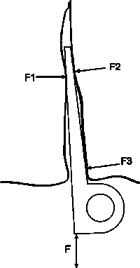
F (insertion or extraction force) = (F1+F2+F3) x Static coefficient of friction
Therefore it stands to reason that the harder you can beat it in the more it will hold, the constraints being hammer size, piton strength and rock strength. In other placements such as a horizontal crack the piton itself will increase the force on the rock (and thus the friction) by leverage or camming, though this is going to very variable, the thicker lost arrows and the channels being much better than soft steel knife blades in this respect. The limitation is then usually the rock strength at the start of the crack, or the piton itself fails.
Some (Dodgy) Theory For Fun
Well, I started out with some heavy calculation on static friction, forces, wedge angles, rock penetration tables and.....
Of course when you think about it the force you will need to get the piton out is going to be near enough the same as the force you needed to put it in, after all friction works equally as well in both directions (see below why this is not exactly so). This is the reasoning in reverse behind pile pull testing in the construction industry. So if you physically can´t beat the thing in any more then that´s it. In real life we stop short of this, usually when the piton barely goes in when we hit it or it starts to collapse or it deforms enough to let you keep driving in up to the head or your arm starts acheing.
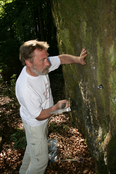
Don´t be gentle-beat the shit out of it!
To calculate what a piton will hold we need the static coefficient of friction and the insertion force:-
Static friction is a complicated subject, especially at higher pressures when the normal static co-efficients are not very accurate and little information on rough steel/rock exists. A quick inclined plane test on a piece of rough steel similar to a piton gave a static coefficient for granite of 0.65 and for limestone 0.75 as a basis for some calculation.
The force of a hammer blow in tons can be taken from this useful table:-
| Size of Hammer | Average Machinist | Experienced Machinist | Exceptional Machinist |
|---|---|---|---|
3/4 lbs |
1.5 |
2.0 |
2.5 |
1 lbs |
2.2 |
3.0 |
3.7 |
1 1/2 lbs |
3.0 |
4.0 |
5.0 |
2 lbs |
4.5 |
6.0 |
7.5 |
2 1/2 lbs |
6.4 |
8.5 |
10.6 |
3 lbs |
11.2 |
15.0 |
18.7 |
My peg hammer head weighs just over 600gr (1.32lbs) and I´m probably in the experienced machinist category so somewhere around 3,5 tons should be reasonable. But the hammering position we were in was not really optimal (the table figures are onto a bench) and my piton hammer has a shorter handle than a standard engineers one so lets say around 2 tons. This is definately getting in the right region because the 8mm thick chrome molybdenum king pin which we beat in to the end of our strength held 19kN (the crack broke at this point), the corresponding 6mm stainless peg started to buckle shortly before we came to the end of our hammering ability and held 1630kg.
Of course the rock´s compressive strength could be the limiting factor, something like a channel with its small contact suface is going to load the rock more and if it is soft the rock will just crumble under the contact points, limiting the maximum force you can apply, in the soft rock we tested in this was the case with the channel pegs as the thin lower legs started to cut in, and one had the feeling you could hammer them in forever. The kingpin design with their wide bearing surface were much better.
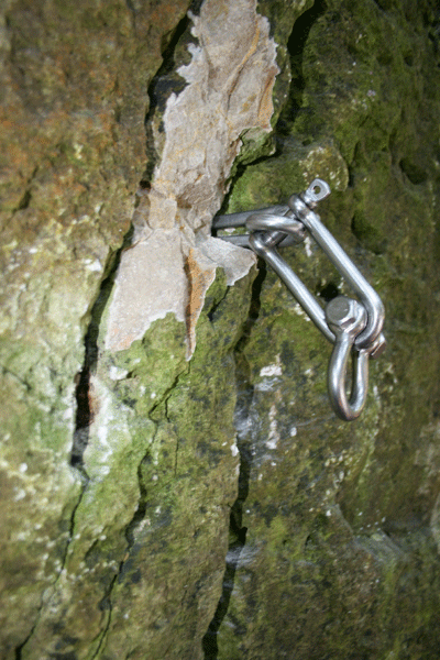
And this happens sometimes
Taking a rock compressive strength of 50N/mm² as is used for bolt testing and probably is a reasonable number for the limestone we where testing in, a required pull out load of 20kN [F] and a static friction coefficient of 0.75 [u] and using Amontons First Law of Friction (or Coulomb´s if you prefer) F=uN we get a required force on the rock of 26,7kN. To withstand this load on the rock it will need to be spread over 530mm². A typical knife blade or king pin achieves this easily with only a few centimeters of contact but a channel with it´s thin walls cannot as we have discovered.
For those unfamiliar with the laws of friction you should remember that increasing the contact area does nothing to increase pull-out resistance for any given forces, this is covered by Amonton´s second law.
The granite block test was performed with on a concrete floor and I was able to drive the pitons in much harder as I was hammering downwards, I performed a rough test by driving a peg between two blocks held together by a hydraulic cylinder and got 45 kN which implies a hammer force of around 3 tons.
And of course you will have noted the force on the rock is 45kN or near enough 4.5tons, so when merrily hammering away look at the size of the block above the piton and ask yourself the obvious question!
Naturally the above is a slight simplification, when you strike the piton some of the kinetic energy of the hammer is converted into a force which overcomes the static friction, The rest of the energy goes to accelerate the piton into the crack. This energy is converted into heat by the sliding resistance which slows the piton down to a stop. (the sliding coefficient is lower than the static one-for granite/steel at about 0.45). With each hammer blow this is repeated with the increasing static friction leaving less energy to move the piton forwards until you reach a point when you cannot apply enough force to overcome the static friction.
The Optimum Taper?
I´ve always had a penchant for shallow tapered pegs and all the ones I have made before were like this. When I started to look at pegs in details I soon found there is no optimum taper as such, the knife blades I have are very gently tapered, the lost arrows vary and some old bongs I have are very steep.
As stated the above theory is a simplification and assumes the piton is in fact parallel but of course this is not the case.
The force producing the friction acts at right angles to the face of the object and as the taper steepens more of this force actually works against you driving the piton in, reducing it´s holding power, though the extent is relatively limited in the thinner pitons, nothing that a big hammer wouldn´t cure!
Naturally cracks are not always parallel-sided and taper has to allow the piton to engage with the rock, a shallow tapered piton won´t work very well in a flared crack, certainly granite cracks have a habit of beoming more flared the wider they are as a result of erosion explaining why my bongs need to have such a steep angle, though obviously to the detriment of their holding power.
The Material Options and What Worked Best.
Soft steel- Poor to piss-poor performance from new and rust easily. They held equally poorly in straight-out testing and horizontal crack pulls primarily because it was impossible to hammer them in any harder before they started to collapse. Highest was 11kN when the eye broke (Stubai 4mm) and the lowest 2kN when a blade peg came out as we were loading the tester. This particular 5mm piton disgraced itself even further only managing an average of 3kN for three pulls in the best case scenario. The manufacturer (Charlet Moser) decided to protect these from corrosion by galvanising them, perhaps overlooking the fact that zinc is one of the metals used in bearings due to its lubricating properties. Of course the galvanising is immediatly destroyed by the rock anyway. In fact a bit of rust is not a bad thing anyway as the static coefficient of granite on lightly rusted steel is 20% higher than on normal steel. The normal 5mm and 6mm blades got an average of 6,8kn in both tests, their softness allowing them to bend and slide out easily and the placement orientation made little difference.
To trust a soft steel peg to hold more than about 5-6kN is pure optimism.
Hard Cast Steel- Not many if any on the market these days, though I tested some older ones. These were both ¼" Lost Arrow /King Pin designs, one from Cassin and the other unmarked but appeared identical. Both had good holding power, at least good enough to break, the eye of the Cassin letting go at 18kN and the other losing it´s eye completely at 22kN. These averaged 16kN straight out. Certainly a pretty good product but impossible to tell the difference between the normal soft steel pitons and these once in place.
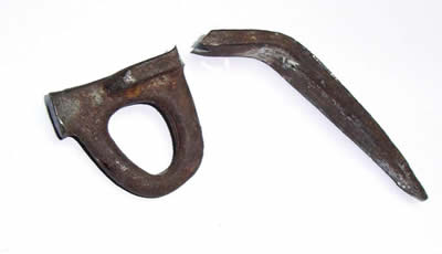
Chrome Molybdenum Steel- As good as it gets perfomance wise but can get stress cracks appearing spontaneously even after years of good service particularly in the bent sheet types. Generations of climbers have relied on Yvon Chouinards finest and a 5/16" Lost Arrow up to its eye in a horizontal granite crack certainly is a fine thing. It only came out when the rock under it started to break up and held over 31kN. In the direct pull tests it was doing well at 19kN when the crack failed totally and certainly would have been much better in if the rock had been stronger.
Nothing wrong with Clog either, 31kN for a 5/8" channel surprised even me though it looked rather sad afterwards and repeat tests were not possible. Its soft rock performance was relatively poor (11kN) as it tended to cut into the rock due to the thin material and never really tok up well. Regrettably Clog saw fit to put their name halfway along the blade so if you meet a small channel driven in it could be anyones, even a soft steel one!
The 1/8" Clog knife blade, a fairly short and wide blade compared with the shapes on the market today was a pleasant surprise, despite its small size it managed 12kN straight out and 14kN in the horizontal crack.
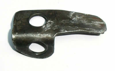
Stainless Steel- Good holding power near chrome-molybdenum. I tried a few designs of these, conventional AISI316 6mm blades holding 13kN straight out but tended to collapse on hammering in. The same design but from a specially hardened material held 17kN in this direction as we could hit it in further. These two were good performers in the horizontal, the soft one getting 24kN and it´s hard buddy 27kN.
The two welded rod designs I tried were a complete contrast, the 6mm ones being poor with 8kN and 11kN in the two directions whereas the 8mm versions held 13kN and 29kN. My idea for an active piton proved not to be so active after they were given a good beating, the results being almost identical with the normal versions at 14kN and 28kN .
One advantage of stainless steel (as well with titanium) is it´s liability to galling, when the pressure is high enought the metal starts to seize onto the rock and removal becomes a question of tearing the material, this was easy to see on the hard rock tests and partially explains the good results
Stainless pitons could suffer from stress corrosion cracking near the sea though with the right alloy this can be eliminated, at a price (€30,000 per ton)
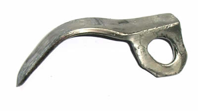
Titanium- Depending on the alloy used performance similar to soft steel or up to the level of stainless steel. We only had a few knife blades to test, aquired on some expedition by Karsten decades ago, and before you ask, they are not from USHBA. These proved to be astoundingly hard and one can only wonder from which part of the Russian space program the material came from.
In the straight-out pull these averaged 12kN which was a good result considering we only got them about 2,5cm in. The flat eye design prevented us from testing in the horizontal crack as the upper block was overhanging.
The sheer cost makes these a non-starter, alone the raw material costs of this little buddy being over €20.
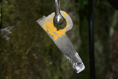
You can see how little engagement there was and just see the areas which started to gall by the torn metal.
How To Raise Piton Holding Power.
Increase the drive-in force is the obvious start, just get a bigger hammer. Most of us with our pathetic little Euro peg hammer would be horrified at the weight of a big wall hammer and certainly this is one way to go but one rapidly comes to the limit of what the piton and the rock will withstand.
The physical size and thus strength (for driving purposes) of the piton is limited by the placement so in the smaller sizes the only ways to improve its performance is go to harder steel and a wider blade, but wider blades start to reduce the placement possibilities. For larger sized pitons climbers have traditionally tried to keep the weight down using thinner steel but there is certainly room to improve channel performance in soft rock by using thicker material and this would also increase the bearing surface on the rock .
Another way is to arrange that the drive-in force will be lower than the extraction resistance, easier said than done. One useful concept would be to use the rock splitting technique of using steel sleeves (shims or counter wedges) which become your point of attatchment and driving a hardened steel wedge between them. As the coefficient of friction of steel to steel is vastly lower than steel to rock you can achieve forces in the hundreds of tons with little effort but of course this is going to be an ugly piece of equipment and may well bring the cliff down! (This is how the Petzl LongLife bolts work, but only in an accurately drilled hole).
An alternative approach is not to depend on friction at all but try to achieve some mechanical engagement to the rock. The bolts used in Elbe sandstone work this way, they are a (long) six sided tapered bar which is driven into a lead filled hole, the force forcing the lead into the pores of the rock. Electrolysis is naturally a topic but they can last amazingly well. Obviously this is impractical in normal cracks but the modern alternative would be just to glue a suitably designed piton in, the difficulty will be getting the glue to surround it correctly.
In-situ - is it good or not?
I started this series of piton tests as I was looking into the possibility of producing stainless steel pitons for permanent placements, primarily in the U.K. where many areas do not allow bolts. In particular the sea-cliffs are a problem as corrosion very soon reduces normal pitons to rust and the in-situ gear is well known to be unreliable.
If you´ve been around a long time and have an encyclopaedic knowledge of piton manufacturers you have some chance of identifying what you are clipping into, otherwise it is going to be pot luck whether it was produced from steel rejected by an Italian car company or the best the U.S (and British) steel industry could produce.
And just looking at the head tells you little about the rest.
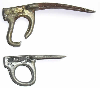
Identical appearing eyes before testing but the top one held 18kN, the lower 4kN!
Rock erosion is a major factor, most who have climbed at Portland will be aware of the `sticking out staples´which show an alarming rate of erosion of the cliff face, perhaps at the rate of 0.5mm per year. Naturally enough a piton in a crack eroding at this rate is going to be useless in a very short time, exactly how short is hard to say but it should not be overlooked that friction forces only work at atomic level. One of the pitons in my tests was removed from an abseil point by hand!
And it doesn´t matter what sort of rock it is, that only affects the speed.
Rock movement- all cliffs are moving, some slowly, some quickly. The cracks are there to prove it! Places like Swanage are moving quickly, one of my earliest first ascents there used a knife blade peg, later that year a Moac and a few years later the entire butress was gone, what use would a corrosion resistant peg be in this situation? There was a well reported court case a few years ago in the U.S.A. concerning 2 pitons which failed, almost certainly due to seismic activity, food for though before you trust your life to a peg.
Freezing is another potential problem, either opening the crack or forcing the piton out, with reports of pitons being loosened by this from the U.S and the Alps.
Climbers from previous generations rightly mis-trust in-situ pegs, rusting or not and anyway usually have a healthy aversion to falling off but the the modern sport and indoor climbing generation will tend to see `shiny´ and think `strong´ with the inevitable consequences.
A piton can only be trusted on the day it was placed and only the climber who placed can give an opinion on its reliability, anything else is only a guess.Reports of pitons found on the ground below climbs or being removed by hand within a few years of placing are commonplace and give a fair indication of their unreliability, as does the number of serious and often fatal accidents involvingin-situ pitons.
Conclusions
The result of producing nice corrosion resistant pitons is that climbers may blindly trust them with potentially fatal result and my feeling is that to put them on the market for permanent placements would be irresponsible and other solutions need to be found.
![]()
Belay Device Theory, Testing and Practice
by Jim Titt, www.bolt-products.com
The following work was part of a project done to gain a better understanding of how belay
devices work and to see how they could be improved. The copyright to all the original parts of
this work are property of Bolt Products, Germany.
All or any parts of this study may only be reproduced if copyright credit is given to Bolt
Products. Germany.
Belay plates are sad, neglected things, there are more studies on rope characteristics and impact forces than one can possibly imagine while the object that controls these forces is hardly ever examined or even considered.
Some tests have been performed and the results vary from useful through helpful to criminally irresponsible with some woeful knowledge of basic physics and material science often being displayed. The only really useful theoretical work on how belay devices work was done by Stephen Attaway but even he suffered from some simplification and the failure to fully appreciate the importance of the rope itself. The best practical tests on various belay devices are those by S. Ratzenburger and the DAV (German Alpine Association).
While many will wish to leave out the theory section with its implication of heavy duty mathematics this would be a mistake, without at least skimming it to get the concepts the rest of this work will probably be meaningless.
For independent comparison tests of a variety of belay devices see the bibliography attatched.
Theory
The Braking Force(s)
To the casual user it appears there are as many as three forces acting in a belay device to provide the nescessary resistance. Bending, friction and squeezing or pinching. In reality the squeezing is only another way of increasing the force pressing the rope against the device to increase the frictional force so can be included in friction.
Knowledge of the relative role of these forces in a belay device is important in understanding how the device works and why the performance changes with varying load and rope diameter.
Bending
Bending force is the force involved in bending the rope, around a karabiner for example, and the amount of force required varies with the bend radius, angle, load, rope stiffness, construction and treatment.
Since the phenomena of reducing sheave diameter increasing the required bending force has been well known and understood in the cordage industry for centuries if not millenia it is suprising that no mention of this occurs in studies of belay devices. In his study of friction in rescue situations Attaway even managed to produce a mathematical model of abseil devices without even mentioning this. As we will see bending is the dominant effect in the great majority of belay devices and it is
important to quantify it in order to understand how a device works. One clue to its importance lies in the heat generated in the device, if the only braking effect was friction then the majority of the energy in a falling/abseiling climber would go into the device which then heats up. To work out the total input, the proportion in the device and the rate of heat loss to the air is not particularly difficult and was performed many years ago by a caver studying long abseils. The end result was so far from reality that it was obvious some other effect was at work.
To calculate the bending force for a rope is shockingly difficult as the modulus of elasticity and friction between thousands of threads in a rope need to be worked out as well as the degree of rearrangement (flattening). It appears from other studies that to a certain extent some of the fibres in the rope are taken past the elastic limit anyway at the small radii climbing equipment uses so one would need to work out the extent that these fail as well. We can surmise this occurs from tests perfomed repeatedly pulling rope through a karabiner or repeatedly abseiling both of which demonstrate that the elongation characteristics of the rope change and its strength is reduced, in other words bending the rope at these radii is permanently affecting the rope.
Instead of calculating the bending force we can look at graphs of efficiency against pulley sheave relative diameters from various sources and we see curves like the one below. Of course we are working in the area outlined in red or possibly a bit higher and it is reasonable to assume this part of the curve is fairly speculative since the studies were interested in the other end of the efficiency scale. The marine cordage industry and the lifting industry already know that small radii are inefficient so they don´t bother to study them much or if they do they don´t publish this information.
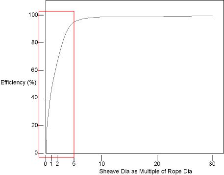
As no information of real use appears to exist it was desirable to measure the bending force in the range we wish to study. The way I did this was to arrange needle roller bearings of 8, 10 & 12mm horizontally on shafts and with a rope over them pull a known weight upwards at a constant speed, varying the wrap angle as required, the difference between the known weight and the measured pull force being the bending force. This was repeated for different loads and rope diameters. This I then expressed as a percentage increase over the original load for convenience. The first pull gives a slightly higher value than subsequent ones by approximately 5% as the rope becomes flattened to a certain extent and retains this so some of the work required to rearrange the threads has already been done. Which value one should take is a matter of conjecture and I used the average of the first three pulls.
Above a certain minimum load the curves become fairly consistent and for clarity I have left the lower load curves off the graph below. They are anyway in a load area we are not interested in, this graph is for forces between 300N and 600N. It is easy to see that the major rise in force increase is in the first 90° with subsequent angular increases having little effect. The thicker the rope and the smaller the bend radius the higher the % force increase we see which is as one would expect.
(The curves are not as perfect as I would wish but the bending test is fairly difficult to do very accurately as the weight of the load cell has always to be taken into account, at my leisure I may try to improve the test and with some other rope diameters but for our purposes the results are perfectly adequate).
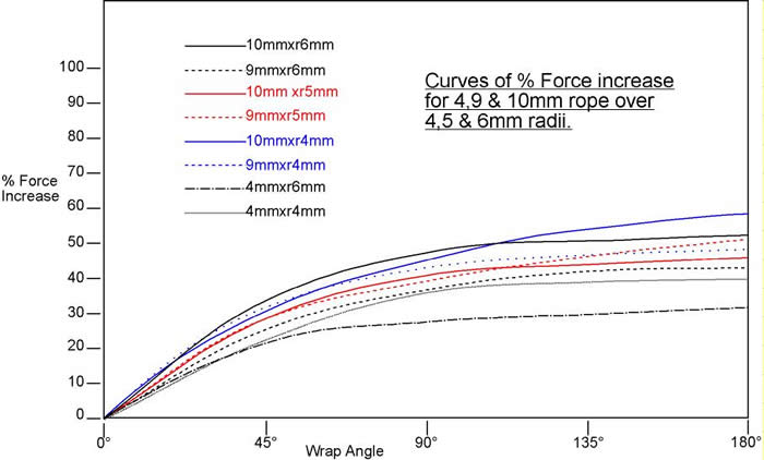
To see what contribution bending makes to a belay device we can now do some calculations. Using a 12mm karabiner and a 10mm rope through a Sticht plate with known radii of 4mm the measured internal bend angles(the bends touching metal) from the hand are 80°, 185° and 42°. The initial force is 300N. From the graphs the first bend has 141,5% more friction so multiplied by 300N we get 424,5N. The second bend has an factor of 151.5% multiplied by the 424,5N gives 643N. The third bend factor is 129% multiplied by 643N gives a total bending resistance of 830N. I then constructed a `frictionless´ belay device from needle rollers dimensionally identical to the Sticht plate above and test pulled this at the same angles, getting a result of 802N which is as close as I could have ever hoped for considering the difficulties in getting the rope bend radius figures. I then pulled the real Stitch plate and got 1320N so as we see the bending is a major (61%)
part of the braking force. By singly testing over a roller and over a 12mm karabiner I could confirm this, the bending force in this case was is 61.3% of the total. The average of 9 combinations of plates with different rope sizes and also using 10/12mm karabiners gives the contribution bending makes as 57%.
(Note: As I habitually use a 10mm karabiner on my belay devices I was interested to see no real difference in braking force compared to using a 12mm one.)
Some manufacturers use a smaller radius than 4mm on the incoming edge, a good example being the Petzl Reverso but if you pull a normal rope hard at 90° to this sort of radius you will see the rope doesn´t completely conform as hand force alone is not sufficient to achieve such a small radius in a rope, in a dynamic situation even less so. Probably something like 3-4mm would be a more accurate figure to use. Too small an incoming radius makes belay plates liable to be grabby or sticky as the weave of the rope mantle tends to hang up on the edge (and climbers have a distrust of sharp edges near ropes) so some restraint is called for here.
Friction
The Laws of Friction have been around a good few hundred years and state:
The force of friction is directly proportional to the applied load. (Amontons 1st Law)
The force of friction is independent of the apparent area of contact. (Amontons 2nd Law)
To work out what is happening in a belay plate should be easy, calculate the normal loads (the ones pushing the rope onto the aluminium) and multiply by the dynamic coefficient of friction for nylon and there you get the frictional force (resistance). In fact Amonton made this easier for us by deriving a formula (below) for loaded ropes going around things (capstan effect) so all you need to do is add up the total of the bends in radians , take the coefficient of friction (mu) and one of the forces, (say your hand grip,) and you can work out the braking force you will achieve. (Those of you that are still following this may know that this law is not exactly true for slipping ropes and the slip regime needs to be taken into account to achieve a Eulerian formula [Belofsky and others] but this is probably going a bit far for something as crude as a belay device with so many other variables!)
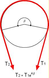
Where e is the exponential function (2.7183), beta the angle in radians and mu the coefficient of friction. T1 is the initial (hand) force and T2 will be the faller force.
Of course in a belay device the rope may well go like this but then it is merely a question of working through each bend at a time but note the section `Combining the Forces´ further down.
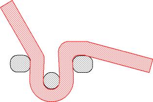
Important is to note that both the angle beta and the coefficient of friction mu are exponential functions and any changes in these has a huge effect on the end results.
First we need to know at least one of the forces and it is logical to use the hand force since this is to a certain extent fixed, or at least lies in a well defined band. Tests by K & K Mauthner show there is a wide variation in the force that can be applied to a climbing rope by hand but the `normal´range is between 150N and 400N. The value of 400N can certainly be considered at the top end for a big strong manual worker on a well used 10mm rope (both I and my brother have verified
this) and is the value used in the Petzl fall calculator but when you get down to a new 9.2mm with a belay bunny on the end this is wildly optimistic. P. Randelzhofer used a value of 209kN as the average value identified by the Mauthners and the DAV tests used a value of 250N with a 9.5mm rope, their tests also included two different climbers belaying the drop tests and the force they could apply lay between these two values. Holding the falls was described as "unpleasantly hard but still controllable" by the test belayers. I settled on 300N as a reasonable compromise as I mostly tested with a 10mm rope. (Naturally you will not achieve this with a 4mm cord, or 7mm for that matter!)
We also require the coefficient of friction. The braking in a belay device has been shown to be dynamic (CMT Italy), that is, the rope is moving and has to be stopped. Therefore we need the dynamic coefficient of friction not the static one which are vastly different (not appreciating this fact rendered the results of at least three published tests useless). At this stage it is important to know that the dynamic coefficient of friction for Nylon 6 is not a constant and varies with pressure
but is relatively constant with velocity, something which the authors of a few research papers really should have found out before starting their work. This naturally also throws a spanner in the works when applying Amontons Second Law. The available quoted figures for the dynamic coefficient vary considerably, mainly because
of the varied test pressures used. For example at 0.05N/mm² which is very low we are given a coefficient of 0.4 whereas industry sources give 0.28-0.3 . Manning in a study of friction for rescue system mechanics tested at what I think is an unrealistically low pressure and measured a coefficient of 0.7, he used a different ASTM test (friction on floor coverings) than those used industrially (rotating steel plates under pressure) which give more normal results for the pressures we are working with. An often quoted value for the dynamic coefficient is in the range we are interested in of 0.16 dropping to 0,10 for water lubrication. Another set of tests (below) by D.Fenz at higher loads shows that the decrease in coefficient with rising pressure is a linear effect in the area he explored and he measured values down to 0.03 for a nylon bearing material. In a moderately loaded device such as a Sticht plate the forces over the back of the karabiner are in the lower levels of pressure used by Fenz and a coefficient of 0.3 for the low loads and 0.16 for higher ones seem reasonable figures to use. (The material used by Fenz was a filled nylon bearing material with a
somewhat lower coefficient then pure Nylon 6).
(The industrial standards for nylon are given against polished (2mm) steel whereas those from Fenz are against stainless steel and from Manning against aluminium. The friction values for these materials is often stated to be different but definitive figures are impossible to come by and the effect itself appears to be very small.)
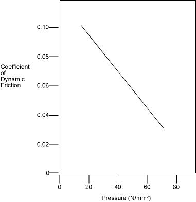
Lastly we need the contact angles, this is a simple matter of measurement though it is helpful to go along with others tests in regard to the operating angles of the rope, if only to be able to compare results. A study by the DAV for their tests gave an angle between the rope to the faller to the belay hand of 137° and this certainly seems a reasonable value to use, a greater angle being fairly impractical in a confined belaying situation. It is not stated whather the angle is before loading or loaded but I assumed it was under load as practically it doesn´t make much sense otherwise. Of course this is only a suitable angle for some devices, others like a GriGri or HMS
have other requirements.
Combining the Forces
Neither the bending or friction occurs in isolation, they work to influence each other in all braking phases through a belay device. As the bending force increases there is more force on the rope which increases the friction force but of course this changes the coefficient of friction. This changed force from both bending and friction effects the next portion of the device and so on.
While each effect can be expressed mathematically to combine these together in one formula is going to be complicated but would be a good topic for someones post-graduate studies!
Some Additional Factors
Vee Grooves
To get more braking power various types of V-grooves are incorporated in the belayer hand side of some devices. The idea behind these is that the downward force of the belayer hand increases locally the normal force per unit area on the rope and hence provides a greater frictional
force (Amontons First Law) though some increase will be lost as the coefficient of friction drops. Too agressive V-slots make the device a bit grabby in use and can eventually damage or prematurely wear the rope, very agressive V slots would take over from the belayer and make lowering almost impossible.. To calculate the extra braking effect is quite difficult so it is better to measure this directly.
Squeezing
In some ways a bit of an urban myth, in most of the plates I have tested the rope isn´t squeezed anywhere in use. Some manufacturers however try to make use of the karabiner being pulled forward under load to squeeze the outgoing rope and provide more friction. Too much bottom angle on the plate however and the krab tends to wedge and the device becomes grabby in use. Probably a reasonable idea but hard to get the right balance. This effect is also to an extent selflimiting as the force pushing the karabiner forward has to be greater than the force trying to straighten the rope, since the first is provided by the initial phase of the device and ones hand and the second by the faller it is easy to see which wins in the end. If you start getting too agressive with this such as using two karabiners to force the rope onto the plate the rope quickly looks unhappy as the outer threads of the rope, already under considerable tension due to the bending moment get forced against the body of the plate, After one pull like this on our test rig the rope was already starting to get furred up with numerous broken threads in evidence. Check the underside rope entry of your plate is nicely rounded! The two karabiner effect is not as great as one has been led to believe and as above is to an extent self limiting, with an increase of ca. 20% in our tests on 9mm and 10mm rope.
This was in good condition until it got the 2 krab treatment!
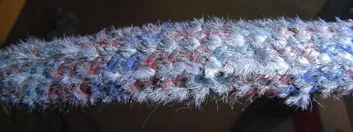
Or with an old,weathered rope and too much squeezing you get this:
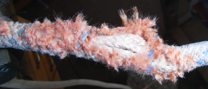
Of course there is the option to squeeze the rope on the incoming side of the device and naturally this can bring enormous benefit as any increase here is magnified through the rest of the device, this is the principle behind the Wild Country SRC, Raptor and the now discontinued Salewa Antz and other similar devices. This also is the basic principle the Petzl GriGri and Edelrid Eddy use though both of these are semi-automatic and the lock-up cannot be controlled by the belayer.
Another way is to arrange the plate so that the loaded rope forces the dead rope onto the device body, this is the principle of the `guide plate´. Not many devices have been made with this principle for lead belaying though the Kong Robot could be used this way. I saw a device using this principle on my first Alpine trip in 1970 which was made from one short chain link welded at an angle to a long one, it appeared home-made but most things were then anyway. Out of curiosity I have made a couple up and played with the angles, around 135° seemed best and and also with two long links instead of one short and one long, while it gave good braking power the rope handling was not really acceptable requiring more delicacy than is usual for climbers. Paying out is relatively good but if you need to take in slack the device rides up into the locking position easily. Here´s a picture for you home experimenters. One way to improve the handling might be to add a spring on the karabiner side as on some older Sticht plates, but I think marketing this weird monster with a spring on the back would be difficult to say the least! (Don´t worry about the cuts through the
links!)
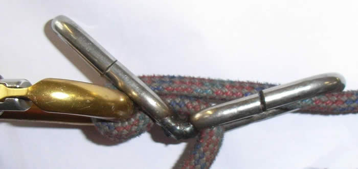
Heat
While not directly affecting the performance of the device to a significant extent (until it melts the rope) the energy of a faller or for that matter an abseiler has to go somewhere and this is going to be in the form of heat. The work of bending is manifested as heat inside the rope, both from the energy required to stretch and compress the threads and the friction between them and would be expected to be retained in the rope, any transfer to the belay device being miniscule. The work of friction produces heat at the interface between the rope and the device and the proportion which goes into which is a function of the relative thermal conductivity of the materials (this is a very complicated subject and the above is a simplification). Since the thermal conductivity of aluminium (250 W/m.K) is 1000 times higher than that of nylon (0.25 W/m.K)it is obvious that the bulk of the energy goes into the device and the karabiner and needs to be transferred into the air to keep the device getting too hot.
A large surface area to increase the transfer to the air and high thermal conductivity to allow the heat to transfer away from the contact point through the device are the obvious requirements. Over the years aluminium has become the material of choice as it it relatively light allowing a larger surface area device to be built without climbers complaining about the weight. It also has a conveniently high thermal conductivity moving the heat rapidly from the contact point. Of course in most devices a lot of the friction is generated at the karabiner and so using an HMS karabiner with more material and a larger surface area is not a bad thing either. One manufacturer produces a belay plate from stainless steel with some interesting if undefined claims regarding reduced heat build up ("it stays a lot cooler") in long abseils. Since
another manufacturer whose device is predominantly stainless steel specifically warns against long (over 50m) abseils due to the danger of overheating there is obviously some difference of opinion over this. The thermal conductivity of stainless steel is vastly lower than that of aluminium (ca. 16 W/m.K) and therefore a higher proportion of the heat energy must go into the rope but conversely the heat going into the device is transferred away from the contact point and into the air less effectively. Naturally enough the rest of the plate is then cooler but the temperature at the contact point with the rope (which melts at relatively low temperatures) will be higher. Personally I think this is the wrong way round, I don´t care if the device is too hot to touch as long as the contact point is ice cold!
For climbers generally the above is all of purely academic interest since they abseil relatively short distances and rarely take 50m factor 2 falls, experience has shown that routine abseiling on the normal lengths of rope cause no problems. The extreme abseilers and cavers however routinely go 200+m and there other devices have to be used and the cavers rack shows the features which keep temperatures down, lots of bends to reduce the dependence on friction and a huge surface area to dissipate the heat.
Testing
All the above helps to build a mathematical model of a chosen design and more importantly shows the relative importance of the various factors in trying to make the perfect plate or analyse the performance of an existing one. In the end one still has to test the device and various methods are used to more or less effect and with more or less expense.
Currently there are no international standards for belay devices for use by climbers and with some thought it is easy to see some of the problems with establishing one. A major difficulty is deciding what parameters to use for braking force, a device perfect for bottom-roping kids on a climbing wall has different performance requirements to one expected to hold a fully equipped climber taking a long factor two fall on ice lines. If some parameters can be decided on, perhaps by having different categories of device, a further major problem is the test rope itself. To be an acceptable standard to international certification bodies some sort of standardised test rope will need to be defined and produced, presumably in various diameters. This is nescessary because ropes vary considerably in their characteristics and allowing the device manufacturers to specify or supply the rope themselves could be open to abuse ( a number of the device manufacturers have commercial interests in rope suplliers or make them themselves), or of course that old UIAA approved hawser-laid No. 4 will come out of the cupboard!
However , as I, like most other testers are to an extent interested in relative performance we can still get usable information from testing and it is virtually unavoidable.
Since the devices operate dynamically any form of static test is completely meaningless, as is shown above in a static test the work of bending is not measured and also the static coefficient of friction can be orders of magnitude higher than the dynamic coefficient. The two dynamic methods
outlined below are currently the best solutions. To get accurate results it is nescessary to test at the loads encountered in real life since, as we have seen above, the factors which affect a devices´ power are all load-dependent and in various ways follow a logarithmic pattern so simple extrapolation is not possible, above a very low limit these factors are not speed-dependent and the actual test speed makes little, if any difference.
One point should be noted, the test rope suffers considerably, particularly on the drop tower testing and the dynamic properties of the rope will alter from test to test. Even in non-drop testing the rope starts to glaze after a few pulls through the more powerful devices and the friction drops noticeably (ca 20%). For this reason it is essential to keep changing the rope and the drop tower method requires considerably more rope than a pull-test set-up.
Drop Testing
The excellent test system devised by Ratzenburger and subsequently used by the DAV and TÜV Süd give the nearest `real world´ results with the benefit of also allowing the slippage to be directly measured. Drawbacks are expense of a drop tower, enormous rope consumption and a slow test cycle. For research purposes it is not very practical as the braking cycle itself is extremely rapid making observation difficult. A simulated hand has also to be constructed which allows controlled
slip of the braking rope at the chosen load (250N for the DAV), if a weight was used it would be subject to inertia due to the rapid acceleration changing the results considerably. (The inertial aspects of belaying have been investigated at length by the CMT in Italy and can be seen reviewed in the work by Moyer [bib.]
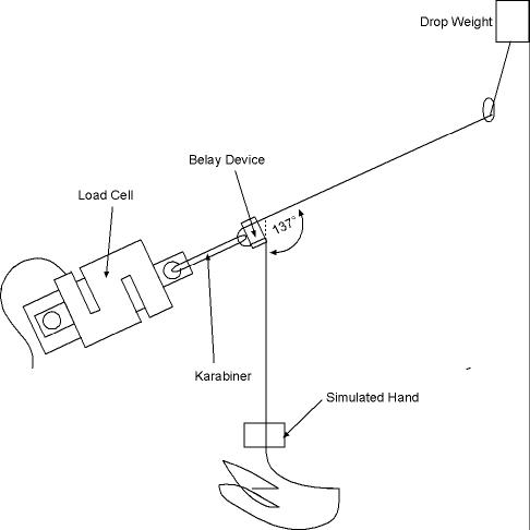
Pull Testing
The system used by Black Diamond and in a modified form by myself is far more suitable for development work as test cycles are enormously faster and rope consumption much lower, the capital costs and space requirements are also a fraction of those of a drop tower. The results are as accurate as a drop tower but the slippage resulting from a defined fall has to be calculated rather than read directly, though of course with the drop tower this also has to be calculated for any other
fall then the standard one. This is not much work however and once a table has been drawn up a matter of seconds. Any standard weights can be used for the braking hand as the movement is at constant velocity so inertia is eliminated.
The first big advantage over the drop tower is that the action of the device can be observed in real time and even interfered with during a test pull, with a drop test one needs a high-speed camera to observe what is happening. The second advantage is the rope can simply be pulled through the
GriGri the required amount to start a new test on a fresh length ( and the lower weight adjusted as required), to re-hoist the weight and change the rope on a drop tower is a time-consuming job. When working with higher loads it is better to change from the GriGri as it will start slipping, adding a stopper knot and increasing the load further (7.4kN) allowed it to over-cam and jam up.
(The idler pulley is adjustable to be able to set the rope angle to compensate for various belay device lengths and to easily test varying angles.Whether the braking angle should be measured from the karabiner or the exit from the device is debatable).
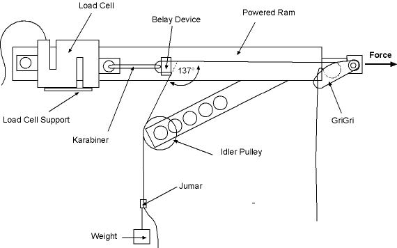
The speed of the test pull is not important since both friction and bending are independant of velocity above a very low value and varying the ram speed made no discernable difference to the test results which also compare well with those from drop tests.
Using The Results
The first thing to remember is to measure the rope angle to the load cell and rope angle to the weight under load because one needs to combine the vectors of the two forces ( load cell measurement and `hand´ force) to get the true braking effect. It is surprising who has overlooked this!
Complex statistical analysis of multiple pulls is fairly unescessary since the results are surprisingly consistent and in real life will vary considerably more depending on factors such as rope type, rope age and condition, belayer hand strength etc, I used the average values of 3 pulls for most work as I primarily was interested in comparative values.
You will notice I have tested with rope (cord) down to 4mm diameter. This helps to get a better idea of the characteristics of the various devices by giving a wider range of values. Additionally I wanted to see if it is possible to make a belay device which could satisfactorily function on this thin a cord!
Some studies such as Ratzenburger give the results as the braking force in kN for a given `hand´force in N but others, including myself prefer to divide the former by the latter to give the power ratio as this seems easier to visualise. It is important to note that this ratio will vary depending on the load so one should always specify the `hand´force in the results. The results are of course specific to the ropes one has chosen to use, soft or hard, dry treated or not but this is inevitable until a "standard test rope" is developed. For published results the make, diameter and treatment of the rope used should be given to allow some comparison to be made.
Strength Testing
Climbers are so used to asking `how strong is it´ that this is inevitably asked about belay devices. For the great majority of devices the loads are extremely low and it would be difficult or impractical to make them as thin as they could be, anyway climbers wouldn´t trust such a filigrane object and so it would never sell. Things are different when the loads are not put through a karabiner as in a Sticht plate but rather are all contained in the device such as a plate in `guide´mode. The best tests for device strength where done by J. Marc Beverly and Stephen Attaway in a excellent and well worth reading paper; `Hang `Em High: How Far Can You Trust Your BelayDevice?´ (see the link in bibliography) where they tied a stopper knot behind the devices (the only way to impose high enough loads without slip) and performed both static and dynamic tests. Reassuringly all but one of the belay devices were able to withstand far higher loads than can in practice be applied before rope slip would occur.
Strength tests of other manufacturers devices were not part of my work.
Varying Braking Hand Strength
Obviously varying the hand strength of the belayer is going to have some effect on the braking force, in fact it makes a large difference and to check this I used my ATC XP as this is a fairly typical device. You can see why it is important to use real-life hand forces not just a convenient small weight!
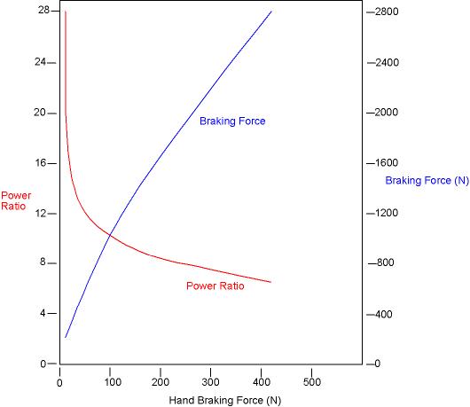
Practice
WARNING
Belay devices in general are limited in their capabilities, something few climbers seem fully aware of. With only one exception no device available on the market is proven to be capable of stopping a climber in a reasonably long factor 2 fall and with most devices the belayer risks severe rope burns and loss of control even in considerably lower (less than 1) factor falls.
The energy involved in a long fall is considerable and the excess energy above that which the device can absorb is transferred into the belayers hand where it is converted into heat by friction. This rapidly causes the skin to heat up and friction burn whereupon an involountary reflex releases the grip. An acceptable amount of slip through a bare hand is variously given as 0.5m and 1.5m depending on the strength of the grip. Alternatively the Petzl Fall Simulator uses a threshhold of 1800J as the acceptable amount of energy before a rope burn warning is given, they allow much more rope (6+m) to slip through than I (and others) would consider reasonable to stop if not wearing gloves and in fact recommend (and illustrate in the instructions for their devices) the wearing of gloves for leader falls, something rarely seen today.
Autolocking Devices
Of these I have only seen independent tests on the Petzl GriGri and the Trango Cinch. While not everyones ideal belay device or even suitable for some types of climbing the GriGri is the only device on the market proven in tests to hold factor 2 falls without damage to itself or the rope as the rope must not be held by the belayer, even though slippage occurs releasing the rope does not cause the faller to be dropped and the belaying action continues until the faller stops. From its design one
can presume this could also the case with the Edelrid Eddy and possibly a few other similar devices but no information on slip is forthcoming from the manufacturers and no independent tests have been performed. The slip loads and slippage for the GriGri are given by the manufacturer for various rope diameters, an exemplary example of how things should be done.
(I tested the GriGri with 4 and 7mm ropes in the interests of continuity but these are outside its operating range and the results are not published. Petzl make a version of the GriGri for thin [7mm] rope which would be interesting to try).
The HMS (Munter or Italian Hitch)
This was developed for climbers (more specifically the karabiner required) by Mario Bisaccia and originally called the Mezzo Barcaiolo (the Italian for Halbmastwurfsicherung) and incidentally has nothing to do with Munter who developed something else. With the exception of the autolocking category this is still the non-plus-ultra of belay devices though it has some handling issues with rope twisting and using double ropes being adventurous. The braking power is head and
shoulders above any current conventional device and the performance with thinner rope is still excellent. About the only other device than the above which could stop a decent factor one fall. The Double HMS is little known outside of guide circles but if you need to lower a large weight this is the knot to use. To belay with it would be a nightmare. On test this was the strongest `belay´ device I have ever tested with a power ratio of 24:1 and defeated the GriGri on the other end of the rope! Surprisingly the rope showed absolutely no signs of distress after this and was probably the gentlest on the rope of all. Powerful enough to break both 4 and 7mm cord using our
standard 300N hand force. Impressed!
Figure of 8
Designed as a lowering device but soon used for abseiling and belaying the humble (if rather large) 8 probably displays the most desirable belaying characteristic of any device with the least percentage loss of performance when used with thinner ropes but sadly only adequate holding power. As with the Munter Hitch rope twisting is a problem as well as using with double ropes. Big and almost extinct as a belay device.
The Sticht Plate/Tuber
Some people differentiate between these but I can´t see any difference in principle and
consider them all to be Sticht plates.
Developed from a chain link used by old sailors as a snubber to a simple plate with slots by Fritz Sticht and on to the latest agressively styled and coloured product there are a multitude of these on the market. Dr Gary Storrick has a collection of over 130 different models and some improvement could have been expected over the last 40 years but in terms of holding power not a lot has changed while handling has improved a bit and the price has changed considerably! In terms of braking power the traditional plate performs equally as well as it´s modern relatives in the standard mode and even begins to outperform them with thicker ropes at the cost of becoming a bit "sticky". In fact testing with a chain link gave even better results than a proper Sticht plate and a number of modern devices, so much for progress! (Aluminium chain link brakes were made by MSR at one time, surely the smallest and lightest device ever produced). The trend to thinner ropes has lead to all manner of high power options based on V slots with some creative names but even these fail to show any significant gain over a basic plate in it´s high power mode i.e. with two
karabiners.
For real high power putting one complete turn around the karabiner pushes the braking power up by over 100% and for abseiling on a single thin rope is a
great idea but beware of rope damage as shown in the pictures earlier, for belaying it is surprisingly manageable but the extra turn tends to flip over a bit like with an HMS and care should be taken to make sure it comes on the spine side of the karabiner. (Hard to explain but easy to see if you play with this at home). Rope twist is also an issue if you are lowering. Of course at this stage you could just as well chuck the plate away anyway and use an HMS! The actual slot length and width in the plate has an effect on the suitability of its use with varying diameter ropes, thinner ropes braking more effectively in smaller slots but this effect isn´t as great as one might think and making the slots smaller has a detrimental effect on the handling not to mention the fingers of steel required to get an older rope in the plate to start with!
Note: In some of the tests by the DAV for Sticht plates relatively higher values than expected were obtained for thin (ca. 8mm) ropes due to them being tested singly. Depending on karabiner and plate design the karabiner was twisting into the plate slot and jamming the rope, particularly in the tuber styles. Naturally one should not rely on this happening in real life and if using double ropes the effect will be much more unlikely.
Test Results
The commercially produced devices (Petzl GriGri, Camp Sticht plate and Black Diamond ATC XP) are included as representative of their type and as yardsticks for comparison with other tests. I have no commercial interest in any of these products, consider them all to be of excellent design and these are in fact my personal belay devices. The Petzl GriGri slip values are from the manufacturers information and are consistent with my own results. The test ropes were:- 10mm Mammut Alto, no treatment. 10mm Tendon Smart, standard treatment. 9mm Roca half rope, no treatment. 7mm & 4mm Tendon (Lanex) accessory cord. The blue line `prototype´ is from tests of a development device made by myself to see what could reasonably be achieved without going to an autolocking type of device.
These tests were performed with a `hand´weight of 300N and correction should be made when comparing these results with other tests. You can use the graph in the section "Varying Hand Strength" to obtain an approximate correction factor.
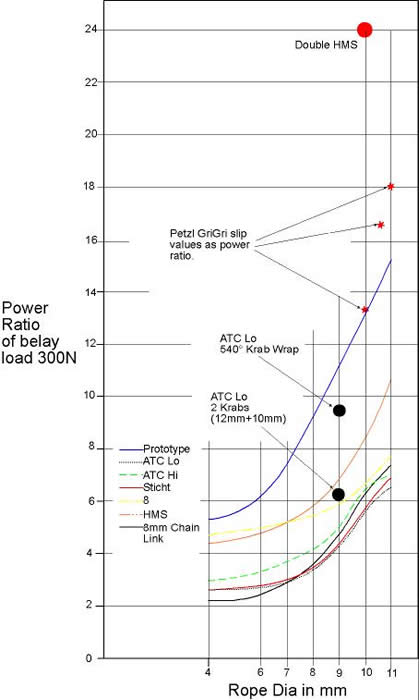
Rope Notes
I have not tested different types of rope as this was not my original objective but noticed a few points on the way:
A soft, new rope gave about 20% less power than an stiff, old and well tested example.
A dirty rope (grit) gave about 20% more power the first time pulled.
A water-soaked rope gave 20% less power than the same dried, the main rope used in this test was not a dry-treated rope as I don´t use these for my climbing.
Most of the pull tests gave a certain amount of glazing on the rope, generally the higher the power of the plate the worse this was and subsequent pulls on the glazed parts gave a loss of power of ca. 20%. The rope companies assure us that this glazing has no effect on the rope and will dissapear with use which it certainly appears to do.
Dry treatment will inevitably lead to lower braking power, both due to the internal lubrication reducing the bending force and the coefficient of friction against the device itself being reduced. Reduced rope friction against the rock and karabiners are desirable characteristics and the increased suppleness of the rope is certainly pleasant but on the other hand knots, belay devices and the gripping ability of the belayers hand are considerably compromised by rope treatment, compounded by the ever thinner ropes. The difference between a battered 11mm wall rope and a super skinny treated one is enormous and something to bear in mind with a novice belayer straight
from an indoor course.What the treatments are and their effects on friction and belaying ability are something rope manufacturers really should be informing us but are not.
Some Conclusions
As with many things, belay device performance is a compromise, a harder braking device stops the climber sooner but loads the system more, a softer one increases the risk of belayer failure.. The limits to this compromise are clearly the ability of any part of the system to withstand the forces applied (i.e.a runner) and the amount of slip through the belayers hand which at a certain point will cause injury and loss of control. To limit the forces on the equipment a more dynamic style of belaying is desirable but the effect is very much a diminishing one as the climber falls further, effectively increasing the fall factor as one can see from this curve of runner load against rope slip derived from various drop tests. The graph is dimensionless in this case but for a normal runner load of 5kN the rope slip is ca ¼ of the fall length after which the cushioning effect has become negligable. Naturally letting the climber fall further may also be a very bad idea!
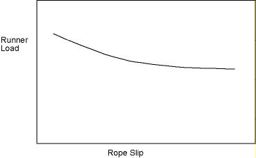
The amount of slippage is limited by the amount of pain and injury the belayer is willing or able to tolerate and at some point in long falls there is going to be a break-even point where the belayer is better off letting go and saving himself from injury since he will anyway be going to be forced to drop the faller, sad but true! The DAV are quite clear in various articles that a large number of the belay devices used are unsuitable for high factor falls, particularly without wearing gloves, some
manufacturers also give warnings but these tend to be much less prominent than the claims of massive holding power in the advertising!
If the system will tolerate it then going to a belay device with a higher braking power is the obvious solution and in most situations this is satisfactory but when climbing on protection of dubious worth then reducing the loading by using a new rope and equipment such as "screamers" may be the only possibility though the effectiveness is reduced the longer the fall..
The most desirable belay device would probably be one which allowed hands-free braking with a pre-determined braking force, allowing the belayer to decide what was an acceptable gear loading taking into account the possible dangers of increased fall distance (i.e. grounding). In the meantime a device which allows the belayer to dynamically control the braking force (wearing glovesas nescessary) while being powerful enough to stop high force falls would be most desirable, the
nearest we get at the moment is the H.M.S, but this has handling issues with double ropes.
Bibliography
A selection of websites with some useful information on belay devices and testing. Some are in German but contain information useful to non-German speakers.
http://storrick.cnchost.com/index.html The non-plus ultra of belay plate collections! Ascenders, abseil devices, belay plates- this website has more than you can believe, over 1200!
http://www.jrre.org/biblio.html The Association of Rope Rescue Engineering and Testing bibliography- links and references to all things concerned with rope.
http://www.xmission.com/~tmoyer/testing/Simulation_of_Climbing_and_Rescue_Belays.pdf Tom Moyer on belay devices with a lot of useful information and some device tests. This was a powerpoint presentation so the dialogue is missing which would help fill up some gaps but still useful.
http://www.mra.org/services/grants/documents/Hang_Em_High_Final.pdf Beverly/Attaway on possible standards and testing of belay devices with static and dynamic destruction (failure) tests of a lot of common devices.
http://www.jrre.org/ropes_101.pdf Stephen Attaway with just about everything you need on calculating fall forces in ropes.
http://www.trango.com/pdfs/BelayDeviceTests.pdf One from Trango, the U.S. manufacturer with some comparison tests done in a novel way!
http://www.oberon.ses.nsw.gov.au/resources/BelayBehaviour.pdf Work on rope stretch in long ropes in rescue back-up belay situations.
http://www.jrre.org/att_frict.pdf Stephen Attaway on friction and deriving Amonton´s capstan formula. Interesting mathematics but flawed.
http://www.mra.org/services/grants/ManningPaper.pdf Timothy Manning on rope friction with an amazing coefficient!
http://www.alpenverein.de/template_loader.php?tplpage_id=85&mode=details&id=1226 DAV/TÜV tests on some devices and how to do drop tests. In German but simple diagrams and tabular results. The original tests for this series and the test design were done by Peter Ratzenberger but are not available online.
http://wbergundsteigen.at/file.php/archiv/2007/2/60-67%20%28die%20bremskraftverst%E4rker%29.pdf More drop tests investigating the relationship between rope diameter and holding power including hand holding power. In German
![]()